


 Abrites AVDI J2534
 Actia Multi-Diag
 Autoland iSCAN
 Bobcat Diagnostic Kit
 BMW ENET
 Bosch Mastertech II J2534
 Bosch MTS 6531
 CAN CLIP RLT2002
 CarDAQ-Plus 3
 Cummins INLINE Datalink
 Dearborn Protocol Adapter (DPA) 5
 Delphi/Autocom DS150E
 DrewLinQ
 Volvo VIDA DiCE
 Derelek USB DIAG 3
 Electronic Data Link (EDL) 2
 Electronic Data Link (EDL) 3
 GM MDI 1
 GM MDI 2
 HEX-V2 VCDS VAG-COM
 Isuzu IDSS IDS MX1
 Isuzu IDSS IDS MX2
 Iveco Eltrac E.A.SY. ECI
 MaxiFlash Elite J2534
 MB Star C6
 Mongoose J2534
 Nexiq USB-Link 1
 Nexiq USB-Link 2
 Nexiq USB-Link 3
 Noregon DLA+ 2.0
 Porsche PIWIS TESTER 3 (PT3G)
 PSA LEXIA 3
 SAE J2434
 Scania VCI 3
 Scanmatik 2 PRO
 SD Connect Multiplexer
 Tactrix OpenPort 2.0
 Toyota TIS Mini VCI
 VAG ODIS VAS5054 Clone
 VAG ODIS VAS6154 Clone
 Volvo VOCOM 1
 Volvo VOCOM 2
 Xentry VCI
 Yanmar Diagnostic Interface Box (IFBOX)


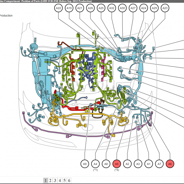
Factory OEM wiring diagrams for the 2018 Audi RS 5 with the 2.9L TFSI twin-turbo V6 Quattro engine. Includes full electrical schematics, connectors, pinouts, and data-bus communication layouts for professional diagnostics and repairs.
The Audi RS 5 2018 Wiring Diagrams Manual delivers full OEM-level schematics for the B9 (Typ F5) platform equipped with the 2.9L TFSI twin-turbo engine. It covers every major electrical and electronic subsystem, ideal for advanced repair, ECU reprogramming, retrofitting, or component-level diagnostics.
Systems Covered
Air Conditioning System (Automatic / Climatronic) – compressor clutch, sensors, actuators, blower motor, and HVAC control circuits
Anti-Lock Braking (ABS/ESP) – hydraulic unit, speed sensors, and control module wiring
Anti-Theft & Keyless Access Systems – immobilizer, alarm siren, door modules, and trunk release circuits
Body Control Modules – lighting, wipers, steering column electronics, and central comfort circuits
Computer Data Lines (CAN, LIN, FlexRay) – full interconnection map for powertrain, chassis, comfort, and infotainment systems
Electronic Power Steering & Suspension – torque sensor, damping control, and actuator wiring
Vehicle Electrical System Control Module – fuse panel, relay assignments, and voltage distribution
Table of Contents
Air Conditioning System
• Climatronic and Non-Climatronic Circuits
• HVAC Sensors and Blend Door Motors
• Fan Control and Pressure RegulationAnti-Lock Brakes (ABS/ESP)
• Wheel Speed Sensors
• Hydraulic Control Unit
• Brake Switch and Control LogicAnti-Theft / Access & Start Authorization
• Door Locking and Touch Sensors
• Alarm Siren and Immobilizer
• Rear Lid and Trunk ControlBody Control Modules
• Comfort and Central Electronics
• Lighting, Mirror, and Window Circuits
• Steering Column and Interior ElectronicsCommunication Networks
• CAN, LIN, and FlexRay Data Lines
• ECU Gateway
• Diagnostic Port IntegrationPower and Ground Distribution
• Fuse Box Layouts and Relays
• Main Junctions and Power Terminals
Technical Highlights
OEM color-coded schematics and connector numbering
Ground, splice, and terminal mapping
CAN/LIN/FlexRay topologies for full ECU integration
Component and module ID cross-references
File Information
Format: PDF (Digital Download)
Language: English
Pages: 164
⚠️ Notice
Digital delivery only — no physical media is shipped. Ensure Adobe Reader or any modern PDF viewer is installed.


Reviews
Clear filtersThere are no reviews yet.