


 Abrites AVDI J2534
 Actia Multi-Diag
 Autoland iSCAN
 Bobcat Diagnostic Kit
 BMW ENET
 Bosch Mastertech II J2534
 Bosch MTS 6531
 CAN CLIP RLT2002
 CarDAQ-Plus 3
 Cummins INLINE Datalink
 Dearborn Protocol Adapter (DPA) 5
 Delphi/Autocom DS150E
 DrewLinQ
 Volvo VIDA DiCE
 Derelek USB DIAG 3
 Electronic Data Link (EDL) 2
 Electronic Data Link (EDL) 3
 GM MDI 1
 GM MDI 2
 HEX-V2 VCDS VAG-COM
 Isuzu IDSS IDS MX1
 Isuzu IDSS IDS MX2
 Iveco Eltrac E.A.SY. ECI
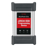 MaxiFlash Elite J2534
 MB Star C6
 Mongoose J2534
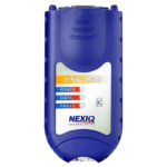 Nexiq USB-Link 1
 Nexiq USB-Link 2
 Nexiq USB-Link 3
 Noregon DLA+ 2.0
 Porsche PIWIS TESTER 3 (PT3G)
 PSA LEXIA 3
 SAE J2434
 Scania VCI 3
 Scanmatik 2 PRO
 SD Connect Multiplexer
 Tactrix OpenPort 2.0
 Toyota TIS Mini VCI
 VAG ODIS VAS5054 Clone
 VAG ODIS VAS6154 Clone
 Volvo VOCOM 1
 Volvo VOCOM 2
 Xentry VCI
 Yanmar Diagnostic Interface Box (IFBOX)


Technical Highlights
Model: CASE D150C Crawler Dozer
Document Type: Factory Hydraulic Schematic
Part Number: RAC #47714315 Rev. E
Format: Color-coded PDF diagram
Language: English
- System Coverage: Full hydraulic architecture – track drive, implement, fan drive, load sense, pilot, and charge systems
Color Legend (page 1 diagram):
• Red = Hydraulic Pressure • Orange = Charge Pump Pressure • Cyan = Return to Tank / Pump Inlet
• Purple = Track Drive • Blue = Track Drive Case Drain • Green = Load Sense
Coverage
Overview
• Color legend for pressure, return, and load sense circuits
• Pressure ratings and hydraulic test points (234 bar travel / 280 bar implement / 350 bar load sense)Main Hydraulic Circuits
• Track Drive System – Dual motor layout with speed sensors and flushing valves
• Implement Functions – Lift, tilt, angle, and ripper circuits with load-sense feedback
• Charge and Pilot System – Charge filters, pressure switches, accumulators, and neutral override valve
• Fan Drive Circuit – Fan speed control and reverse valves integrated with pilot logic
• Load Sense System – Dynamic pressure compensation for pumps and actuatorsComponent Reference List (77 items) Includes Track Drive Motors (1 & 8), Oil Cooler (12), Hydraulic Reservoir (24), Lift & Tilt Cylinders (41–42), Fan Drive Motor (68), Ripper Spool (56), and Load Sense Relief Valve (46).
Performance Data
• Main System Pressure – 420 bar
• Charge Pressure – 25–30 bar
• Pilot Pressure – 16 bar
• Load Sense – 203–210 bar
• Implement Pressure – 280 ± 5 bar
Delivery
The download link will be sent to your email instantly after payment.


Reviews
Clear filtersThere are no reviews yet.