


This technical wiring manual contains the complete electrical schematics for the digital mirror replacement system used in MAN TG3 trucks.
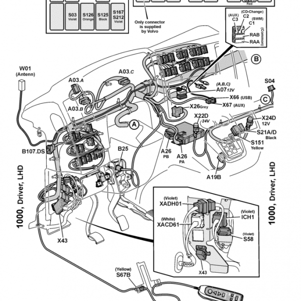
The diagrams include the full control architecture for mirror display units, roof-mounted camera modules, heating circuits, CAN communication lines, fuse routing, and electrical supply connections.
All circuits include connector identifiers, system references, and grounding architecture required for advanced diagnostics, repair, or retrofit work.
Mirror Replacement System Components
Mirror display left (A1548.1)
Mirror display right (A1549.1)
Camera bracket roof left (B1250.1)
Camera bracket roof right (B1251.1)
These electronic mirrors replace the conventional exterior mirror assemblies and transmit camera signals to internal display units.
Electrical Supply and Fuse Protection
The system is powered through:
Central electrical system A100
Fuse mirror replacement left (F1583.1)
Fuse mirror replacement right (F1584.1)
Each display and camera circuit receives a protected supply through the vehicle electrical system.
CAN Bus and Communication Wiring
The mirror replacement system communicates through:
CAN_H communication line
CAN_L communication line
O-CAN network integration
This communication allows the mirror displays to transmit camera data and status signals to the vehicle cluster and control systems.
Camera Signals and Heating Circuits
The diagrams include full wiring for:
Camera signal lines (Signal_CAM-1 / Signal_CAM-2)
Camera shielding connections
Heating supply circuits (HEAT_P1 / HEAT_P2 / HEAT_N)
Temperature signal wiring
These circuits support camera image transmission and heating functions for stable operation in cold environments.
Driver Control Interface
Mirror replacement control switches include:
Driver control switch S1485
Passenger control switch S1484
These switches replace the traditional mirror control switch when digital mirrors are installed.
Diagnostic Use Cases
This wiring manual is essential for diagnosing:
digital mirror display not working
roof camera signal missing
mirror heating malfunction
CAN communication mirror faults
fuse or power supply issues
mirror control switch problems
cluster communication errors
Compatible Vehicles
MAN TG3 platform trucks, including:
TGX
TGS
TGM
TGL


Reviews
Clear filtersThere are no reviews yet.