


Technical Highlights
Engine coverage: 1.8 TSI (132 kW) and 2.0 TSI (162 kW)
Model years: 2013–2014
Engine codes covered: CJS, CJSB, CHH
Fuel system: FSI / MPI direct injection
Turbocharging and charge-air systems
Complete engine removal and installation procedures
Factory torque values, tightening sequences, and safety instructions
OEM Škoda service documentation (Edition 11.2013)
Delivery
The download link will be sent to your email instantly after payment.
Full Contents
Technical data
Technical data
Engine number
Engine characteristics
Self-diagnosis
Self-diagnosis, safety measures, cleanliness regulations and directions
Safety precautions when working on fuel supply system
Safety measures for vehicles with start/stop system
Releasing pressure in the high-pressure fuel system
Cleanliness rules for fuel supply system
Test conditions for fuel supply system
Safety measures for fuel injection and ignition systems
General notes on injection system
General notes on ignition system
General instructions for charge air system
Additional instructions for air-conditioning system assembly work
Removing and installing engine
Engine trim panel
Removing and installing engine trim panel
Engine removal and installation
Removing engine
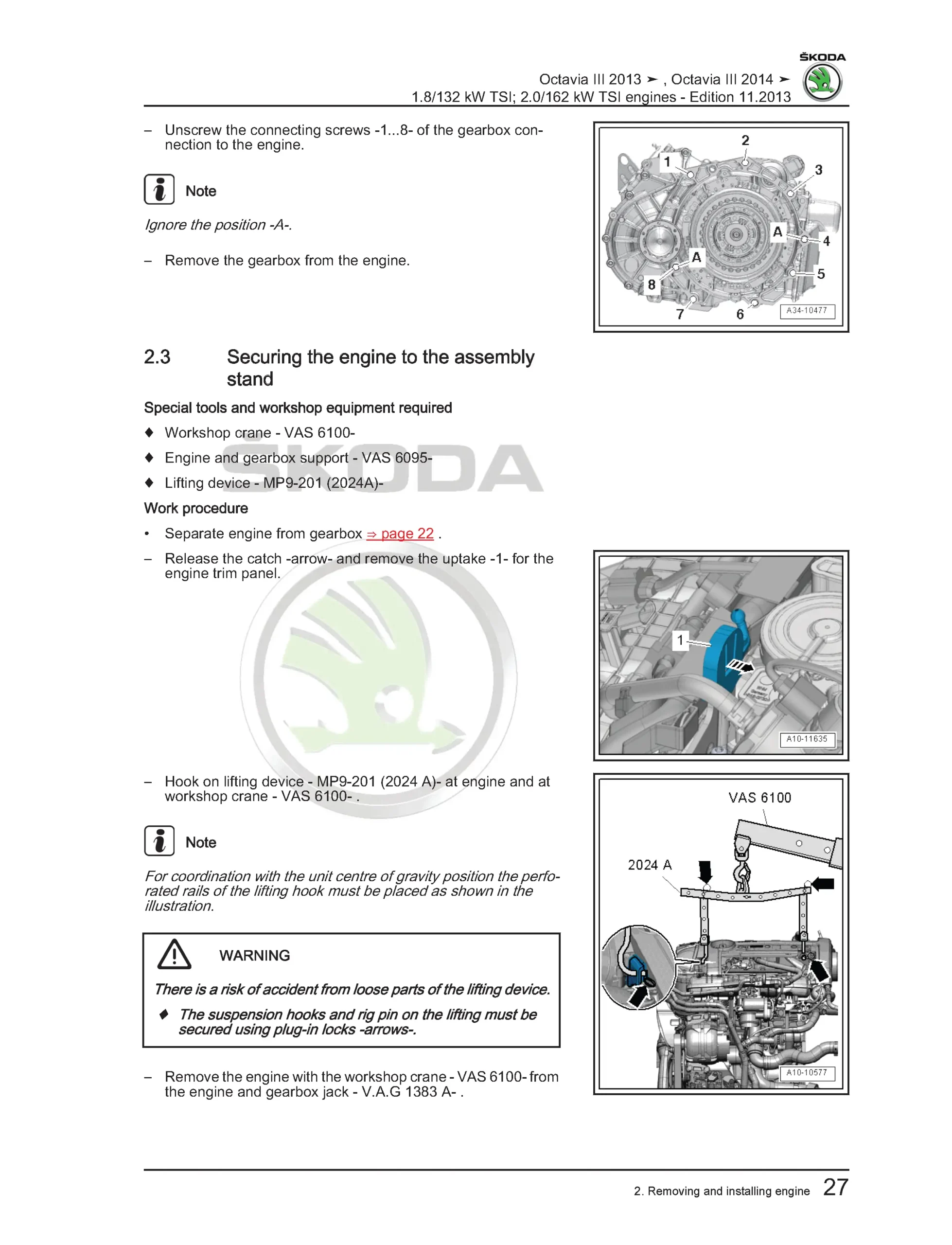
Separating engine from gearbox
Securing engine to assembly stand
Installing engine
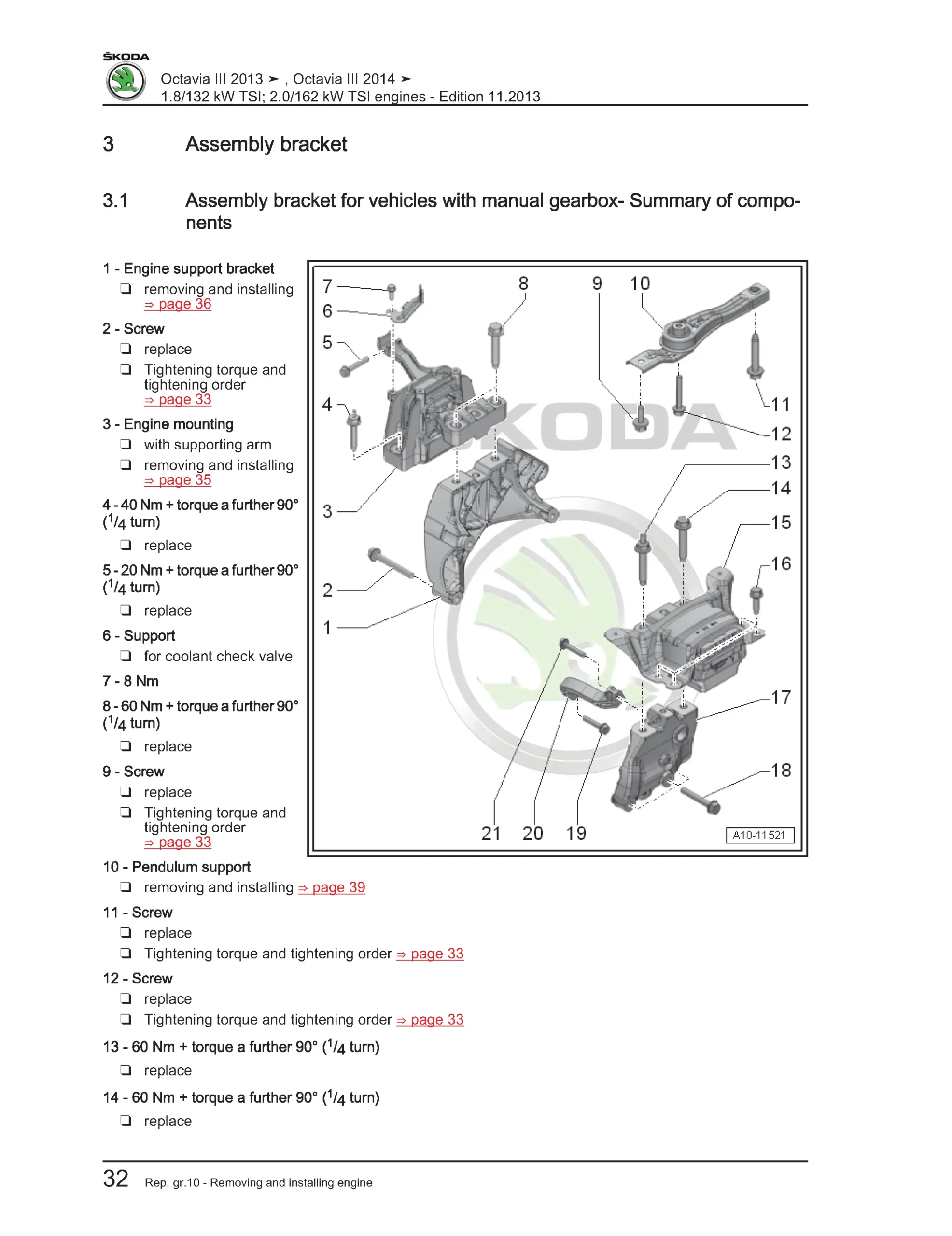
Assembly bracket and mountings
Assembly bracket for manual gearbox
Assembly bracket for DSG gearbox
Removing and installing engine mount
Removing and installing engine support
Removing and installing gearbox mount
Removing and installing pendulum support
Checking assembly bracket setting
Adjusting unit mounting
Crankshaft group
Cylinder block – belt pulley side
V-ribbed belt drive – summary of components
Removing and installing poly V-belt
Removing and installing tensioner pulley
Removing and installing auxiliary unit bracket
Removing and installing ribbed belt pulley
Cylinder block – gearbox end
Sealing flange and flywheel
Summary of components
Removing and installing dual-mass flywheel
Removing and installing sealing flange on gearbox side
Crankshaft
Summary of components
Assigning bearing shells
Replacing needle bearing
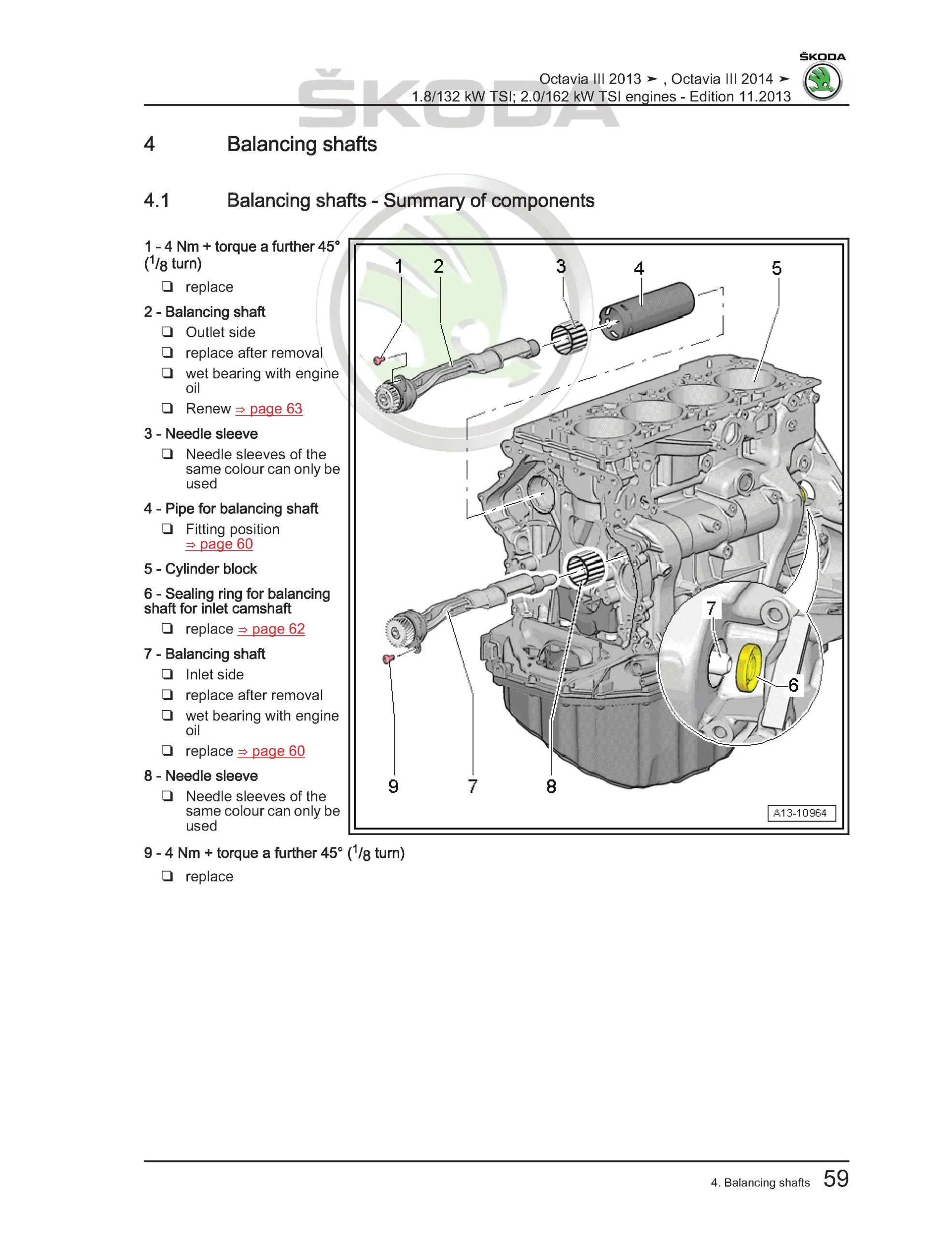
Balancing shafts
Summary of components
Removing and installing inlet camshaft balancing shaft
Replacing sealing ring
Removing and installing exhaust camshaft balancing shaft
Pistons and conrods
Summary of components
Removing and installing piston
Inspecting piston, piston rings and cylinder bore
Separating new conrod
Cylinder head and valve gear
Timing chain covers
Summary of components
Removing and installing camshaft adjustment valves N205 / N318
Removing and installing top timing chain cover
Removing and installing bottom timing chain cover
Replacing crankshaft V-ribbed belt pulley seal
Chain drive
Camshaft timing chain – summary of components
Removing and installing camshaft timing chain
Balancing shaft timing chain – summary of components
Removing and installing balancing shaft timing chain
Checking timing chain length
Checking valve timing
Cylinder head
Summary of components
Removing and installing cylinder head
Checking compression
Testing combustion chamber tightness
Valve gear
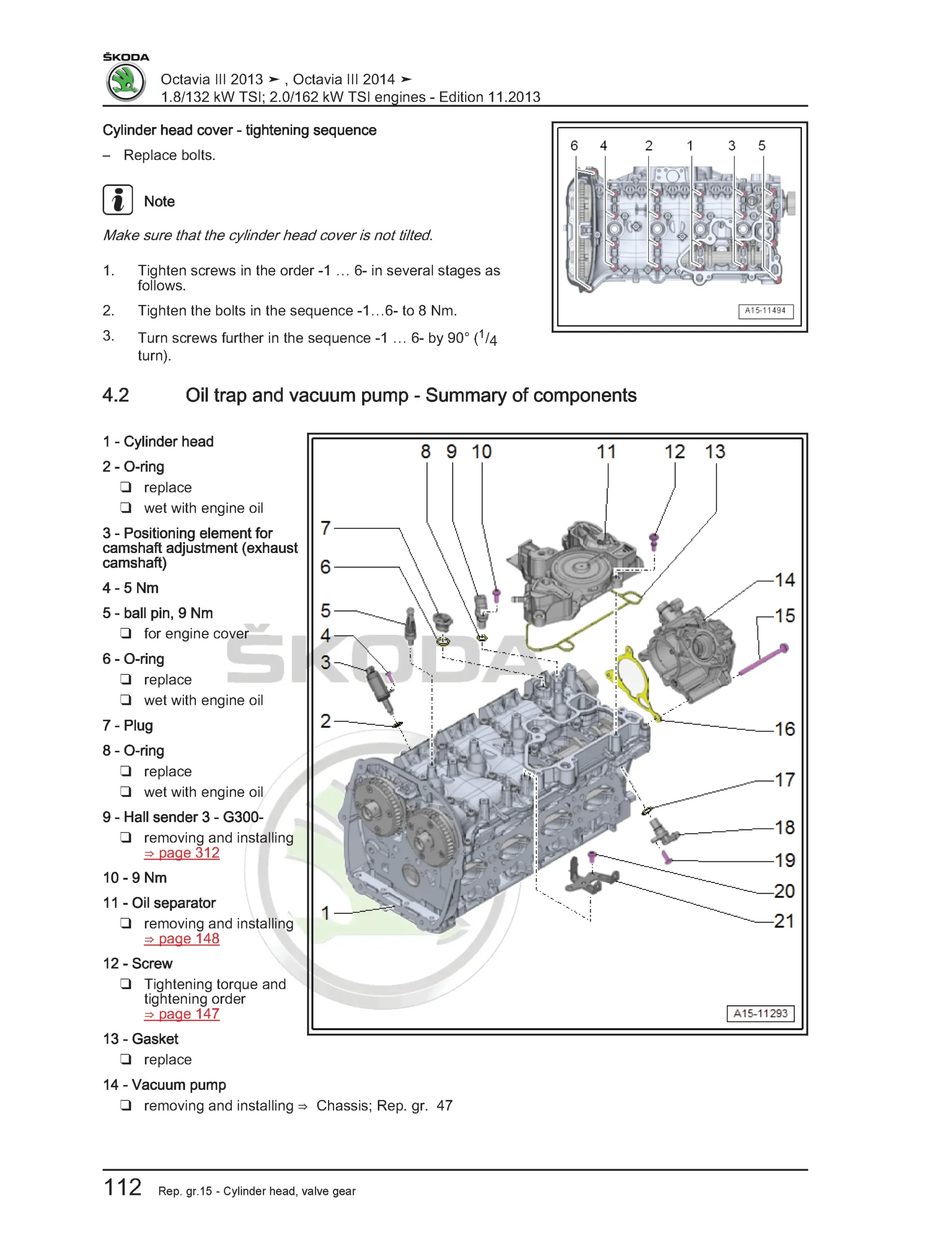
Summary of components
Oil trap and vacuum pump – summary of components
Removing and installing camshafts
Installing ball for camshaft slide
Replacing valve stem seals
Checking valve guides
Valve dimensions
Lubrication
Oil sump and oil pump
Summary of components
Removing and installing oil level and oil temperature sender G266
Removing and installing oil sump bottom part
Removing and installing oil sump top part
Removing and installing oil pump
Auxiliary unit bracket with oil filter and engine oil cooler
Summary of components
Removing and installing engine oil cooler
Removing and installing mechanical switch valve
Crankcase ventilation
Summary of components
Removing and installing oil separator
Oil pressure system
Oil pressure switch – summary of components
Removing and installing piston cooling nozzle control valve N522
Removing and installing oil pressure switches F22, F378, F447
Removing and installing oil pressure control valve N428
Testing oil pressure
Checking oil pressure for piston cooling nozzles
Cooling
Cooling system
Coolant hose connection diagrams for manual and DSG gearboxes
Draining and filling coolant
Checking cooling system for leaks
Coolant pump and temperature control
Summary of components
Coolant recirculation pump
Coolant valves for gearbox and cylinder head
Removing and installing coolant pump
Removing and installing coolant recirculation pump V51
Removing and installing coolant shut-off valve N82
Removing and installing positioning element N493
Removing and installing coolant temperature senders G62 and G83
Coolant pipes
Summary of components
Removing and installing front coolant pipe
Removing and installing top coolant pipe
Radiator and radiator fan
Summary of components
Removing and installing radiator fan
Removing and installing fan shroud
Fuel supply system
Fuel tank
Front-wheel drive – summary of components
All-wheel drive – summary of components
Extracting fuel
Removing and installing fuel tank
Fuel delivery unit and fuel gauge senders
Summary of components
Removing and installing fuel delivery unit
Removing and installing fuel gauge senders G and G169
Checking fuel delivery unit
Fuel pump control unit
Removing and installing J538
Suction spray pump
Separating push-on couplings
Accelerator pedal
Summary of components
Removing and installing accelerator module
Activated charcoal filter system
Summary of components
Removing and installing activated charcoal filter
Turbocharging / supercharging
Exhaust gas turbocharger
Summary of components
Removing and installing turbocharger
Removing, adjusting and setting charge pressure regulator V465
Charge air system
Charge air cooling – summary of components
Removing and installing charge air cooler
Removing and installing charge pressure sender G31
Checking charge air system for leaks
Mixture preparation – injection
Injection system layout and installation locations
Air filter
Summary of components
Removing and installing air filter housing
Intake manifold and fuel distributor
Intake manifold – summary of components
Fuel distributor FSI – summary of components
Fuel distributor MPI – summary of components
Removing and installing intake manifold
Removing and cleaning throttle valve control unit J338
Injectors
Removing and installing FSI injection valves
Removing and installing MPI injection valves
Cleaning FSI injection valves
Sensors and senders
Removing and installing fuel pressure sender G247
Checking fuel pressure sender
Removing and installing low-pressure fuel pump control unit G410
High-pressure pump
Summary of components
Removing and installing high-pressure pump
Lambda probes
Summary of components
Removing and installing Lambda probe G39
Removing and installing Lambda probe after catalytic converter G130
Engine control unit
Removing and installing engine control unit J623 without protective housing
Removing and installing engine control unit J623 with protective housing
Removing and installing engine noise speaker
Exhaust system
Front exhaust system
Summary of components
Removing and installing exhaust pipe
Middle and rear exhaust system
Summary of components
Replacing exhaust sections
Removing and installing exhaust system
Aligning exhaust system free of stress
Aligning exhaust tailpipes
Inspecting exhaust system for leaks
Ignition system
Ignition system
Summary of components
Removing and installing ignition coils with output stage
Removing knock sensor G61
Removing and installing Hall sender G40
Removing and installing Hall sender G300
Removing and installing engine speed sender G28


Reviews
Clear filtersThere are no reviews yet.