


 Abrites AVDI J2534
 Actia Multi-Diag
 Autoland iSCAN
 Bobcat Diagnostic Kit
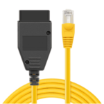 BMW ENET
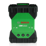 Bosch Mastertech II J2534
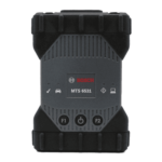 Bosch MTS 6531
 CAN CLIP RLT2002
 CarDAQ-Plus 3
 Cummins INLINE Datalink
 Dearborn Protocol Adapter (DPA) 5
 Delphi/Autocom DS150E
 DrewLinQ
 Volvo VIDA DiCE
 Derelek USB DIAG 3
 Electronic Data Link (EDL) 2
 Electronic Data Link (EDL) 3
 GM MDI 1
 GM MDI 2
 HEX-V2 VCDS VAG-COM
 Isuzu IDSS IDS MX1
 Isuzu IDSS IDS MX2
 Iveco Eltrac E.A.SY. ECI
 MaxiFlash Elite J2534
 MB Star C6
 Mongoose J2534
 Nexiq USB-Link 1
 Nexiq USB-Link 2
 Nexiq USB-Link 3
 Noregon DLA+ 2.0
 Porsche PIWIS TESTER 3 (PT3G)
 PSA LEXIA 3
 SAE J2434
 Scania VCI 3
 Scanmatik 2 PRO
 SD Connect Multiplexer
 Tactrix OpenPort 2.0
 Toyota TIS Mini VCI
 VAG ODIS VAS5054 Clone
 VAG ODIS VAS6154 Clone
 Volvo VOCOM 1
 Volvo VOCOM 2
 Xentry VCI
 Yanmar Diagnostic Interface Box (IFBOX)

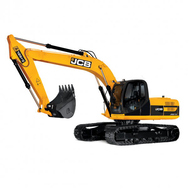
 – Tier IV SCR Diagnostic and Urea Dosing System Manual")
This manual explains the Controller Area Network (CAN-BUS) diagnostic principles used in CASE M-Series Dozers and other CNH Tier IV machines.
It introduces controller networking, voltage logic, and EST-based troubleshooting for CAN BUS 1 & 2 systems linking the ECM, UCM, AIC, Denox Module, and Telematics controllers.
Key learning points:
CAN BUS architecture: layout, twisted-pair topology, termination resistors (120 Ω), and node addressing.
Signal logic: CAN Hi (2.5–3.5 V DC) and CAN Lo (1.5–2.5 V DC).
EST testing procedures: voltage and resistance diagnosis, controller status interpretation, and fault isolation.
M-Series Dozer application: dedicated diagrams on pages 10–11 illustrate small and large dozer CAN BUS maps with diagnostic port placement.
Coverage
Introduction to CAN Technology
Origin (Bosch & Intel 1984)
Use in Automotive and Industrial applications
Purpose of CAN Systems
Replacing mechanical components with electronic modules
Networked communication for shared signals
Benefits of CAN
Reduced wiring and connectors
Improved diagnostics and sensor sharing
Enhanced reliability and signal accuracy
Terminology
ECU, EMC, BUS, CAN Hi/Lo voltage ranges, Terminator resistors
CAN Circuit Construction
Twisted pair wiring and magnetic field cancellation
Shielded vs unshielded configurations
Overview of CAN System
Digital message exchange between processors (page 5)
External and internal terminators illustration
Testing Procedures with EST and DVOM
Voltage test for good circuit (2.5–3.5 V range)
Offline controller diagnosis (shorted BUS)
Resistance test for termination integrity (60–30 Ω)
Short and open circuit fault examples
Troubleshooting Guide
Step-by-step fault isolation via controller disconnects
Interpretation of “ONLINE/OFFLINE” status on EST
M-Series Dozer CAN BUS Layouts
Small Dozer Network (UCM, AIC, Telematics, ECM)
Large Dozer Network with Denox Module and NOx sensor integration
Delivery
The download link will be sent to your email instantly after payment.


Reviews
Clear filtersThere are no reviews yet.