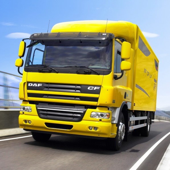
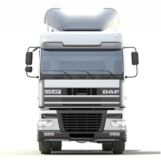
DAF LF/CF/XF105 Series Bodybuilder Guidelines Manual Guide with high-quality graphics and illustrations.
Language: English
Format: PDF
Pages: 438
Sections:
- General
- Purpose
- Addresses to contact
- Verification of superstructure
- Statutory requirements
- Vehicle specification and layout drawings
- Weight distribution
- Period of bodying and storage
- Painting the chassis and components
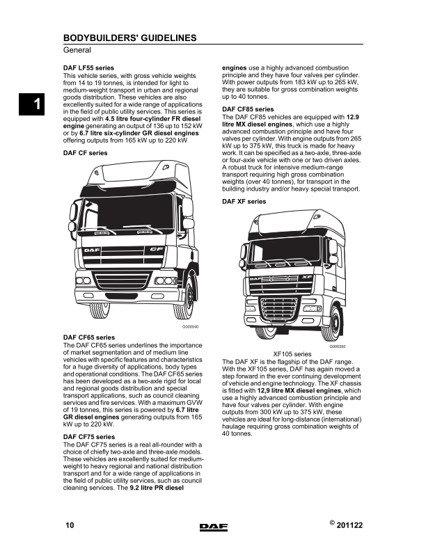
- DAF vehicle range
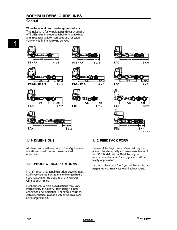
- Dimensions
- Product modifications
- Feedback form
- CHASSIS INFORMATION
- Levelling the chassis
- Drilling of holes
- Welding on the chassis
- Modifying the rear overhang
- Wheelbase modifications
- Attachment of components to the chassis
- Replacing rivets by bolts
- Inlet and exhaust systems
- Fuel system
- Chassis and cabine related dimensions
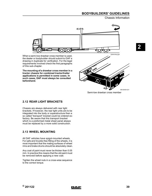
- Drawbar cross member
- Rear light brackets
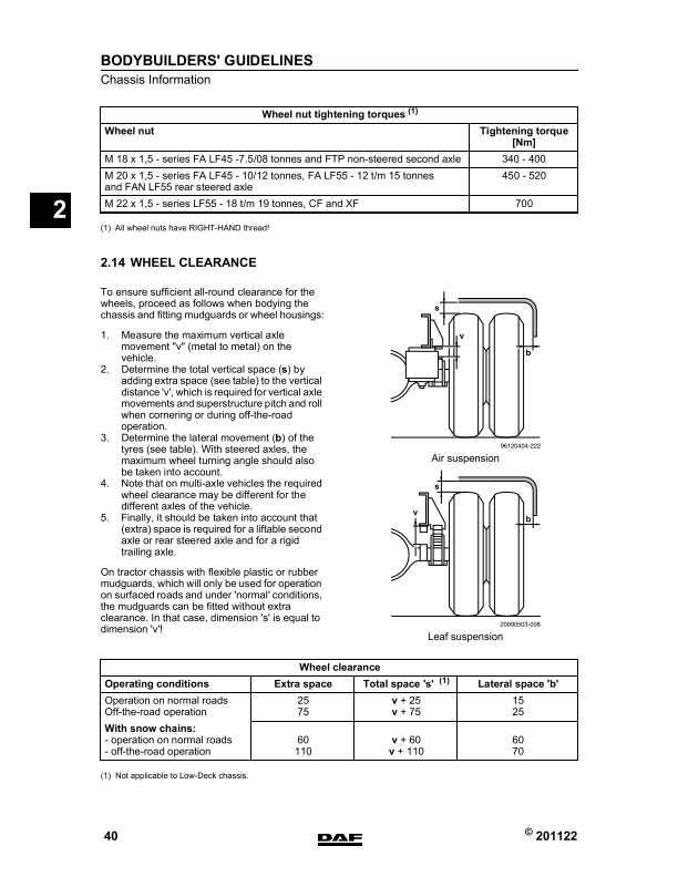
- Wheel mounting
- Wheel clearance
- Location of the mudguards
- EC-approved rear underrun protection
- Automatic lubrication
- GENERAL INFORMATION ON SUPERSTRUCTURES
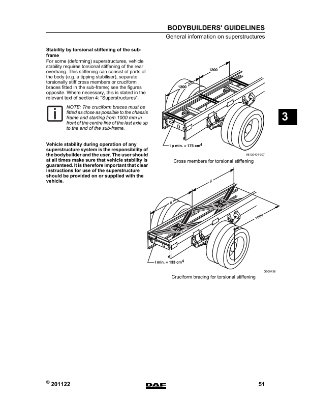
- Superstructure with sub-frame
- BAM’s – body attachment methods
- First attachment point
- Type of superstructure/BAM matrix
- BAM instructions, general
- FA LF45
- FA LF55
- FA LF55 18t
- FA CF65
- FA CF and XF
- FAR/FAS CF and XF
- FAG CF
- FAN LF
- FAN CF and XF
- FAT CF and XF
- FAC/FAX CF
- FAD CF and XF
- FAK CF and XF
- Superstructures SUPERSTRUCTURES
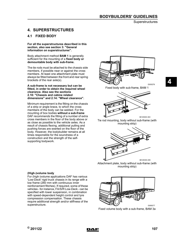
- Fixed body
- Body with tail lift
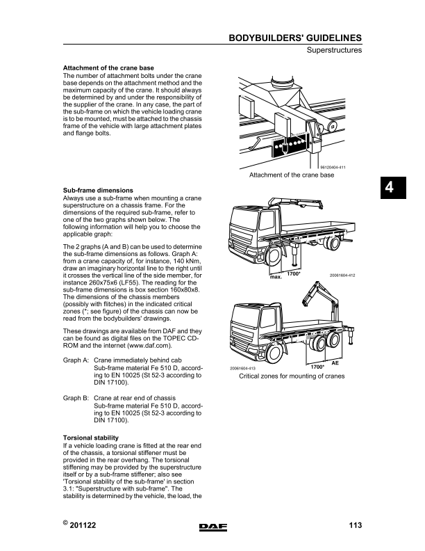
- Vehicle loading cranes
- Tipper bodies
- Tankers
- Concrete mixers and concrete pumps
- Public utility vehicles
- Front-mounted equipment
- TRACTORS
- CAB INFORMATION
- Cab modification
- Maximum permissible additional cab weights
- Accessories mounting positions
- Setting the roof spoiler
- PTO AND OTHER ENERGY CONSUMERS
- General
- Power take-offs (PTO’s)
- PTO specification, general
- Clutch-independent PTO
- Clutch-dependent PTO
- First PTO
- Second PTO
- Transfer box
- PTO operation
- Compressed air system
- Air feed, tipper preparation
- Heating system
- ELECTRICAL SYSTEM GENERAL
- General
- Safety instruction
- Circuit diagram
- DATA COMMUNICATION SYSTEMS
- Data communication CAN SAE J1939 / ISO 11898 (including FMS)
- Data communication CAN open
- Data communication ISO 11992/2 & 11992/3
- Body Builders’ Module (Optional)
- ELECTRICAL SYSTEM LF SERIES
- LF series cab switch and connector locations
- LF series bulkhead connections
- LF and CF65 series chassis connections
- LF series accessories connection headershelf
- LF series accessories connection dashboard
- LF series power supply
- LF series radio preparation
- LF series telephone preparation
- LF series anti-theft protection
- LF series ESC control
- LF series PTO control / protection
- LF series FMS system
- Refuse preparation LF Series
- LF series trailer connection points
- ELECTRICAL SYSTEM CF SERIES
- CF series cab switch and connector locations
- CF series bulkhead connection overview
- CF75 and CF85 series chassis connections
- CF series accessories connections
- CF series accessories connection in dashboard
- CF series power supply
- CF series radio preparation
- CF series CB preparation
- CF series telephone preparation
- CF series anti-theft protection
- CF series refrigerator preparation
- CF series LED preparation immobiliser / Alarm
- CF65 Series ESC control
- ELECTRICAL SYSTEM XF SERIES
- XF series cab switch and connector locations
- XF series bulkhead connection overview
- XF series accessories in headershelf
- XF series accessories connection in dashboard
- XF series power supply
- XF series radio preparation
- XF series CB preparation
- XF series telephone preparation
- XF series anti-theft protection
- XF series refrigerator preparation
- XF series LED preparation immobiliser / Alarm
- XF series microwave preparation
- XF series chassis connections
- XF series ESC control
- XF series FMS system
- XF series trailer connection points
- Connector 6V refuse collector
- Connector 12D body builder 374
- Connector 23K body functions
- Connector 56A accessories
- Connector 56W refuse collector
- Connector 182C power supply
- Connector 183C power supply
- Connector 238C radio system
- Connector A000 trailer system (ISO1185 type 24N)
- Connector A001 trailer system (ISO3731 type 24S)
- Connector A004 trailer system (ISO7638)
- Connector A007 accessories 24V 2-pole
- Connector A011 accessories 12V 2-pole
- Connector A038 accessories
- Connector A043 driver seat connector
- Connector A058 trailer system (ISO12098)
- Connector A068 (chassis – ESC system)
- Connector A070 accessories 8-pole)
- Connector A076 telephone
- Connector A088 taillift system 7-pole
- Connector A095 application refuse collector
- Connector A097 FMS system
- Connector A098 FMS system
- Connector A100 HD-OBD diagnose
- Connector A102 body builder 8-pole
- Connector A103 bodybuilder 12-pole
- Connector A104 spare wiring 18-pole
- Connector A105 Bodybuilder CAN system 7-pole
- Connector A106 CAN-cab 9-pole
- Connector A113 garbage truck
- Connector A117 trailer 13-pole
- Connector A122 hydraulic platform 9-pole
- Connector A123 hydraulic platform 21-pole
- Connector A125 hydraulic platform feed through
- Connector A126 FMS 2-pole 405
- Connector A134 refuse feed through wire
- Connector A138 FMS 12-pole
- Connector A139 – A140 extra camera
- Connector D318 (ECU) Toll Collect
- Connector D365
- Connector D347
- ECN code number overview 410
- PART NUMBERS
- Mountings
- Flange bolts
- Electric connector parts
- Electric connector parts cabine (CF75-85 and XF Series)
- Electric connector parts cabine (LF Series)
- Electric cable contour lights chassis
- Extension piece for the LF mud guard
- Indication lamps
- Switches
- CVSG Gauges
- Adapters air system
- Lowered drawbar components
- Miscellaneous parts
Delivery: The download link will be sent to your email instantly after payment.



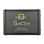 Abrites AVDI J2534
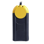 Actia Multi-Diag
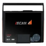 Autoland iSCAN
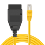 BMW ENET
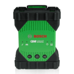 Bosch Mastertech II J2534
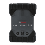 Bosch MTS 6531
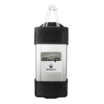 CAN CLIP RLT2002
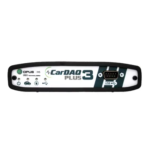 CarDAQ-Plus 3
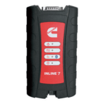 Cummins INLINE Datalink
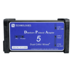 Dearborn Protocol Adapter (DPA) 5
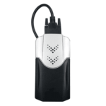 Delphi/Autocom DS150E
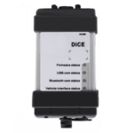 Volvo VIDA DiCE
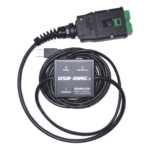 Derelek USB DIAG 3
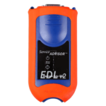 Electronic Data Link (EDL) 2
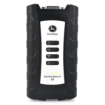 Electronic Data Link (EDL) 3
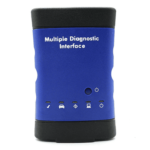 GM MDI 1
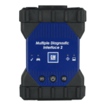 GM MDI 2
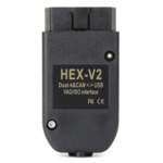 HEX-V2 VCDS VAG-COM
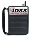 Isuzu IDSS IDS MX1
 Isuzu IDSS IDS MX2
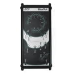 Iveco Eltrac E.A.SY. ECI
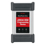 MaxiFlash Elite J2534
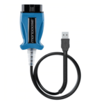 Mongoose J2534
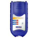 Nexiq USB-Link 1
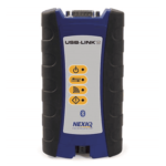 Nexiq USB-Link 2
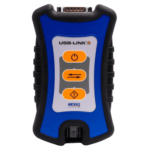 Nexiq USB-Link 3
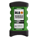 Noregon DLA+ 2.0
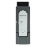 Porsche PIWIS TESTER 3 (PT3G)
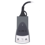 PSA LEXIA 3
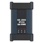 SAE J2434
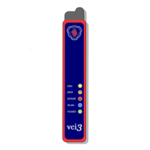 Scania VCI 3
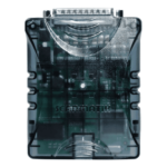 Scanmatik 2 PRO
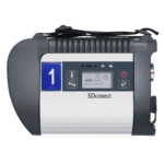 SD Connect Multiplexer
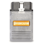 Tactrix OpenPort 2.0
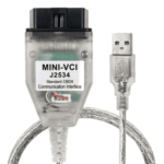 Toyota TIS Mini VCI
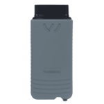 VAG ODIS VAS5054 Clone
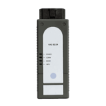 VAG ODIS VAS6154 Clone
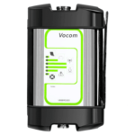 Volvo VOCOM 1
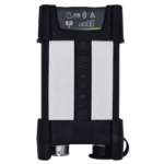 Volvo VOCOM 2





Reviews
Clear filtersThere are no reviews yet.