Get comprehensive factory-level support for your SsangYong Tivoli & XLV X102 with the official Service Repair Manual and wiring Diagrams. This complete documentation is essential for DIY enthusiasts, mechanics, and professional technicians. It offers step-by-step procedures and full electrical schematics for accurate maintenance, repairs, and diagnostics.
Manual Includes:
✔ Detailed Service Procedures – Engine, transmission, suspension, brakes, HVAC, etc.
✔ Wiring Diagrams – Full electrical schematics for troubleshooting and repair.
✔ Technical Specifications – Torque settings, fluid types, and service intervals.
✔ Diagnostic Instructions – Fault code explanations and test procedures.
✔ Illustrated Diagrams – Clear visuals for component location and assembly.
Delivery:
The download link will be promptly delivered to your email upon completing the checkout process.SsangYong Tivoli & XLV X102 – Service Repair Manual & Wiring Diagrams Content
- WML_201: Engine mechanical system
- WML_202: Lubrication system
- WML_203: Cooling system
- WML_204: Fuel system
- WML_205: Intake & exhaust system
- WML_206: Emission control system
- WML_207: Engine electrical system
- WML_208: Starting system
- WML_209: Charging system
- WML_210: Engine control system
- WML_211: Ignition system
- WML_212: Special tools
- WML_213: Diagnostic procedures
- WML_501: Body Construction Overview
- Construction types
- Materials used
- Anti-corrosion coatings
- WML_502: Body Repair Techniques
- Welding guidelines
- Panel replacement
- Structural reinforcements
- WML_503: Exterior Components
- Front bumper, hood, doors
- Roof & quarter panels
- Liftgate and tailgate
- WML_504: Interior Trim and Safety
- Dashboard and airbag systems
- Seats and child restraint
- Carpet, console and interior panels
- WML_507: Sealing, Deadener, Undercoating
- Application locations
- Materials used
- WML_508: Major Welding Points
- Spot welding diagrams
- Panel joining points
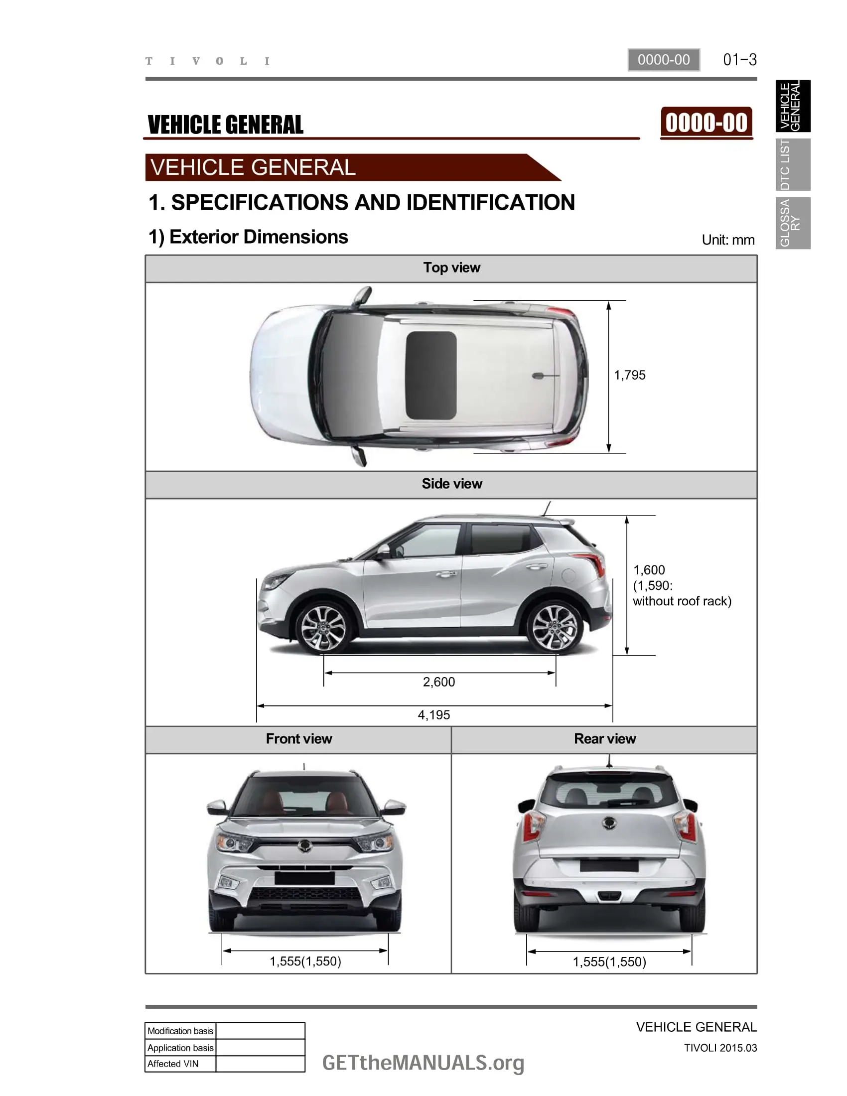
- Major dimensions
- Vehicle identification
- Specifications and check items
- Recommended fluids and lubricants
- Maintenance services
- CAN communication structure
ul>Reading wiring diagrams Terminal number checking Part location via connector number
- 8210-00: Harness component locations
- 8210-00: Ground / Splice Pack
- 8211-01: Engine Extn
- 8211-01: Engine Room
- 8211-01: Engine Main
- 8211-01: Main Harness
- 8211-01: Floor
- 8211-01: Roof
- 8211-01: Doors
- 8211-01: Tail Gate
- 8211-01: Rear Passenger
- Engine Room Fuse & Relay Box
- Indoor Fuse Box
- ENGINE SYSTEM
- 1462-01: Starting / Charging
- 1490-01: ECU (G16DF)
- CHASSIS SYSTEM
- 3691-07: TCU (6-A/T)
- 3280-17: AWD Coupling Unit
- 4892-00: ABS/ESP
- 4610-00: EPS
- 4190-00: TPMS
- ELECTRICAL SYSTEM
- 8210-01: Diagnosis (CAN)
- 8010-01: Cluster
- 8810-01: Airbag Unit
- 8712-03: SKM
- 8710-01: BCM
- 8520-01: Power Windows
- 7110-01: Door Lock Circuit
- 7850-01: Outside Mirror
- 7840-20: Defogger
- 7810-01: Front Wiper / Washer
- 7830-03: Rear Wiper / Washer
- 7410-01: Driver Power Seat
- 7410-01: Front Seat Warmer / Vent
- 7510-01: Rear Seat Warmer
- 8310-01: Head Lamp
- 8310-01: VSM
- 8310-01: Head Lamp Leveling
- 8310-01: Tail Lamp / Fog Lamp
- 8320-20: Rear Fog Lamp
- 8610-16: Interior Tail Lamp
- 8310-01: Turn Signal / Hazard Lamp
- Specifications
- Essential Tightening Torques
- Oil Seal and Tolerances
- Special Tools
- Diagnosis Items for Each Symptom
- Cautions for Operation & Handling
- TCU Control Function
- Operating Components
- Power Transfer Process
- Emergency Mode
- CAN Configuration
- Specifications
- Overview
- Major Changes
- Tightening Torque
- Gear Ratio & Power Flow
- Shifting Mechanism
- Gear Shift Indicator (GSI)
- Specifications
- Tightening Torque
- Overview
- Components
- Operating Process
- Specifications
- Tightening Torque
- 2WD Model Components
- AWD Model Components
- Torque Steer Explanation
- Specifications
- Notices (Towing, Lifting)
- Specifications (Front, Rear - 2WD & AWD)
- Wheel Alignment Specifications
- Suspension Components & Torque
- Overview
- Mounting Locations
- Assembly Types
- Front Suspension (MacPherson Strut)
- Rear Suspension (Torsion Beam - 2WD)
- Rear Suspension (Multi-link - AWD)
- Wheel Alignment Principles (Toe, Camber, Caster, Trim Height)
- Specifications (Disc Types, Booster, Fluids)
- Brake System Warning Lights
- Special Tools
- Troubleshooting Table
- Brake Operation & Noise
- System Check (Pedal Height, Travel, Booster, Switch)
- Front Brake Inspection
- Rear Brake Inspection
- Overview and Hydraulic Operation
- Components (2WD & AWD)
- Structural Details
- Brake Hydraulic Line Layout
- Stop Light Circuit Diagram
- VEHICLE GENERAL
- SPECIFICATIONS AND IDENTIFICATION
- SPECIFICATIONS AND CHECK ITEMS
- CAN COMMUNICATION CONFIGURATION
- ELECTRIC DEVICE GENERAL INFORMATION
- HOW TO READ ELECTRICAL WIRING DIAGRAM
- HOW TO CHECK TERMINAL NUMBER OF VERIFIED OPTIONS
- PART LOCATION ACCORDING TO CONNECTOR NUMBER
- POWER DISTRIBUTION
- FUSE / RELAY
- ENGINE ROOM FUSE / RELAY BOX
- ENGINE ROOM FUSE / RELAY BOX CIRCUIT
- IP - FUSE / RELAY BOX
- IP - FUSE / RELAY BOX CIRCUIT
- VOLTAGE STABILIZER MODULE
- FUSE / RELAY
- CIRCUIT
- ENGINE
- STARTING / CHARGING
- GLOW CONTROL UNIT
- ENGINE CONTROL UNIT (ECU)
- HEATING VALVE (D16DTF)
- FUEL PUMP
- CHASSIS
- TORQUE / AUTOMATIC TRANSMISSION
- AWD COUPLING UNIT
- ABS/ESP
- EPS (Electric Power Steering)
- TPMS (Tire Pressure Monitoring System)
- ELECTRICAL SYSTEM
- DIAGNOSIS (CAN)
- CLUSTER
- AIRBAG UNIT
- SKM (Smart Key Module)
- RCM (Restraint Control Module)
- POWER WINDOW
- DOOR LOCK CIRCUIT
- OUTSIDE MIRROR
- DEFOGGER
- FRONT WIPER / WASHER
- REAR WIPER / WASHER
- DRIVER POWER SEAT
- FRONT SEAT WARMER/VENT
- REAR SEAT WARMER
- HEAD LAMP
- VSML (Vehicle Stability Management Lamp)
- TAIL LAMP
- STOP LAMP
- INTERIOR / DOOR LAMP
- PARKING AID SYSTEM (FRONT/REAR)
- BACK UP LAMP / REARVIEW MIRROR
- SUNROOF
- AUDIO
- NAVIGATION AUDIO
- HORN
- QUALITY LIMITED / POWER CIRCUIT
- AIR CONDITIONER SYSTEM
- STEERING WHEEL HEATING
- DC/DC CONVERTER
- AC INVERTER
- ENGINE
- CONNECTOR/GROUND
- WIRING HARNESS
- COMPONENTS LOCATION
- CONNECTOR, GROUND / SPLICE PACK
- CONNECTOR/GROUND DETAILS
- WH ENGINE EXTN
- WH ENGINE ROOM
- WH ENGINE MAIN
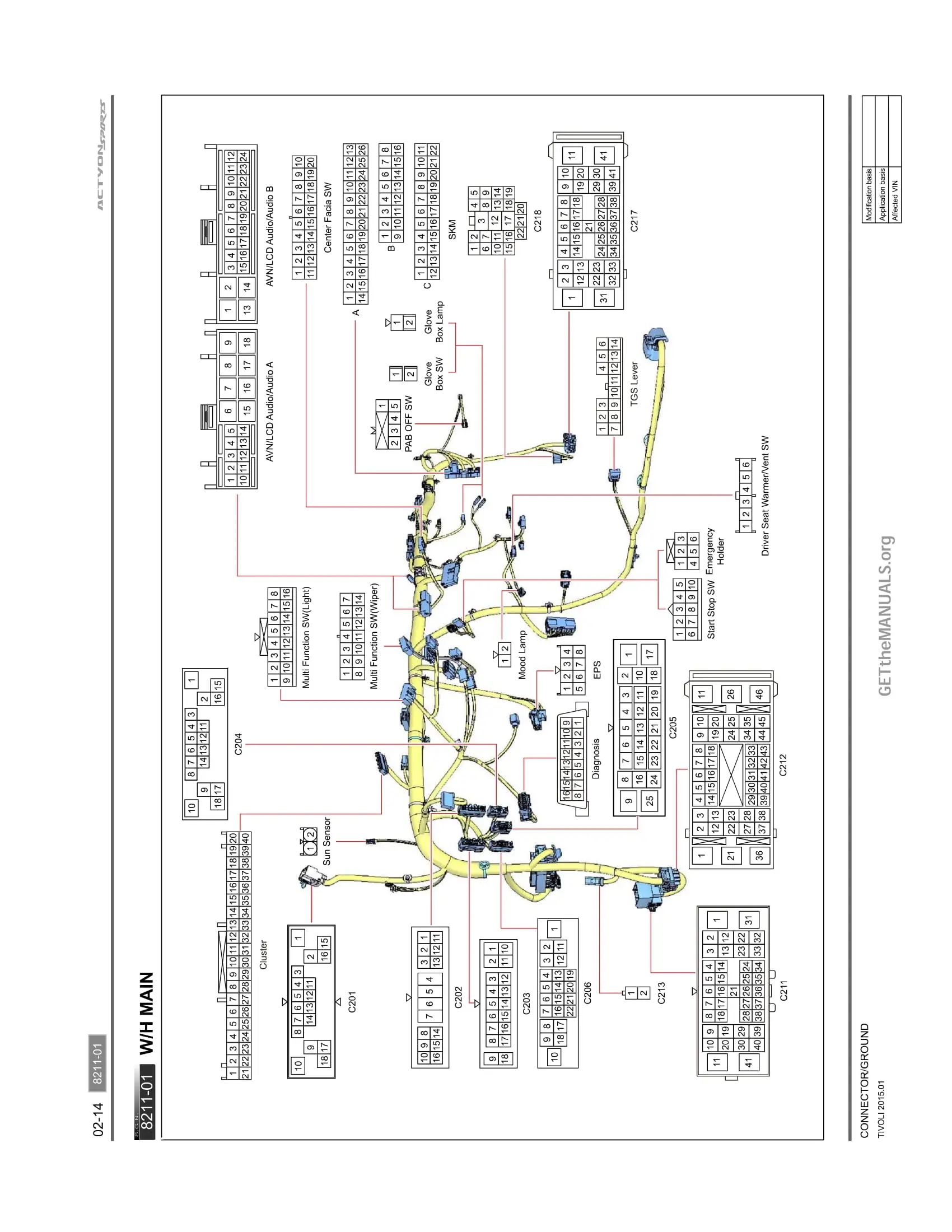
- WH MAIN
- WH FLOOR
- WH ROOF
- WH DOOR
- WH TAIL GATE
- WH PAS/REAR
- WIRING HARNESS



 Abrites AVDI J2534
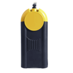 Actia Multi-Diag
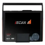 Autoland iSCAN
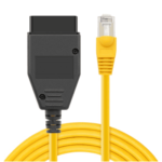 BMW ENET
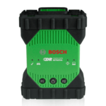 Bosch Mastertech II J2534
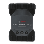 Bosch MTS 6531
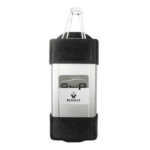 CAN CLIP RLT2002
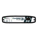 CarDAQ-Plus 3
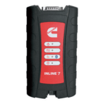 Cummins INLINE Datalink
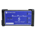 Dearborn Protocol Adapter (DPA) 5
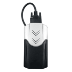 Delphi/Autocom DS150E
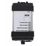 Volvo VIDA DiCE
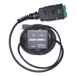 Derelek USB DIAG 3
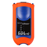 Electronic Data Link (EDL) 2
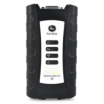 Electronic Data Link (EDL) 3
 GM MDI 1
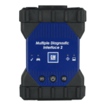 GM MDI 2
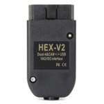 HEX-V2 VCDS VAG-COM
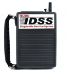 Isuzu IDSS IDS MX1
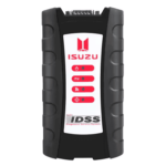 Isuzu IDSS IDS MX2
 Iveco Eltrac E.A.SY. ECI
 MaxiFlash Elite J2534
 Mongoose J2534
 Nexiq USB-Link 1
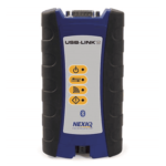 Nexiq USB-Link 2
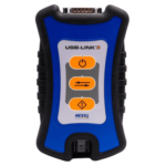 Nexiq USB-Link 3
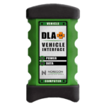 Noregon DLA+ 2.0
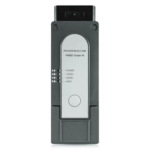 Porsche PIWIS TESTER 3 (PT3G)
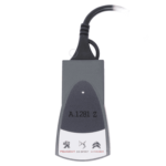 PSA LEXIA 3
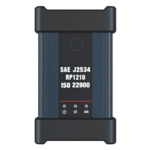 SAE J2434
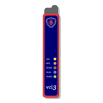 Scania VCI 3
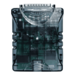 Scanmatik 2 PRO
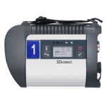 SD Connect Multiplexer
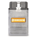 Tactrix OpenPort 2.0
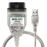 Toyota TIS Mini VCI
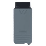 VAG ODIS VAS5054 Clone
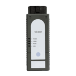 VAG ODIS VAS6154 Clone
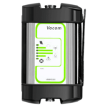 Volvo VOCOM 1
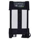 Volvo VOCOM 2




Reviews
Clear filtersThere are no reviews yet.