VW 4-Cylinder Direct Injection Engine (1.5 l Engine, 4V, EA 211, Turbocharger) OEM Workshop Manual with high-quality graphics and illustrations.
Format: PDF
Pages: 440
Delivery: The download link will be sent to your email instantly after checkout.
Covered VW Vehicles
- Arteon 2018 ➤, Golf 2017 ➤,
- Golf Sportsvan 2018 ➤,
- Golf Variant 2017 ➤, Passat 2015 ➤,
- Passat 2019 ➤ , Passat Variant 2015 ➤ ,
- Passat Variant 2019 ➤, Polo 2018 ➤,
- T-Roc 2018 ➤, Tiguan 2016 ➤,
- Touran 2016 ➤
Covered Engine IDs:
Repair Group:
- Repair Group
- Technical data
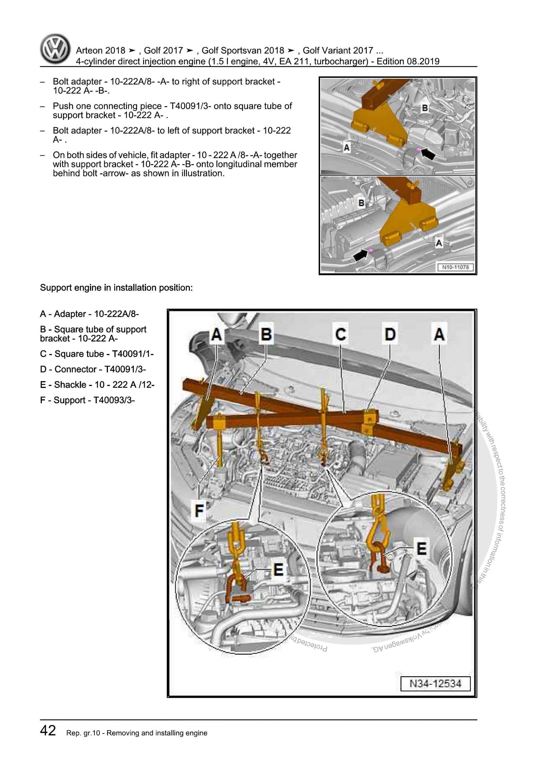
- Removing and installing engine
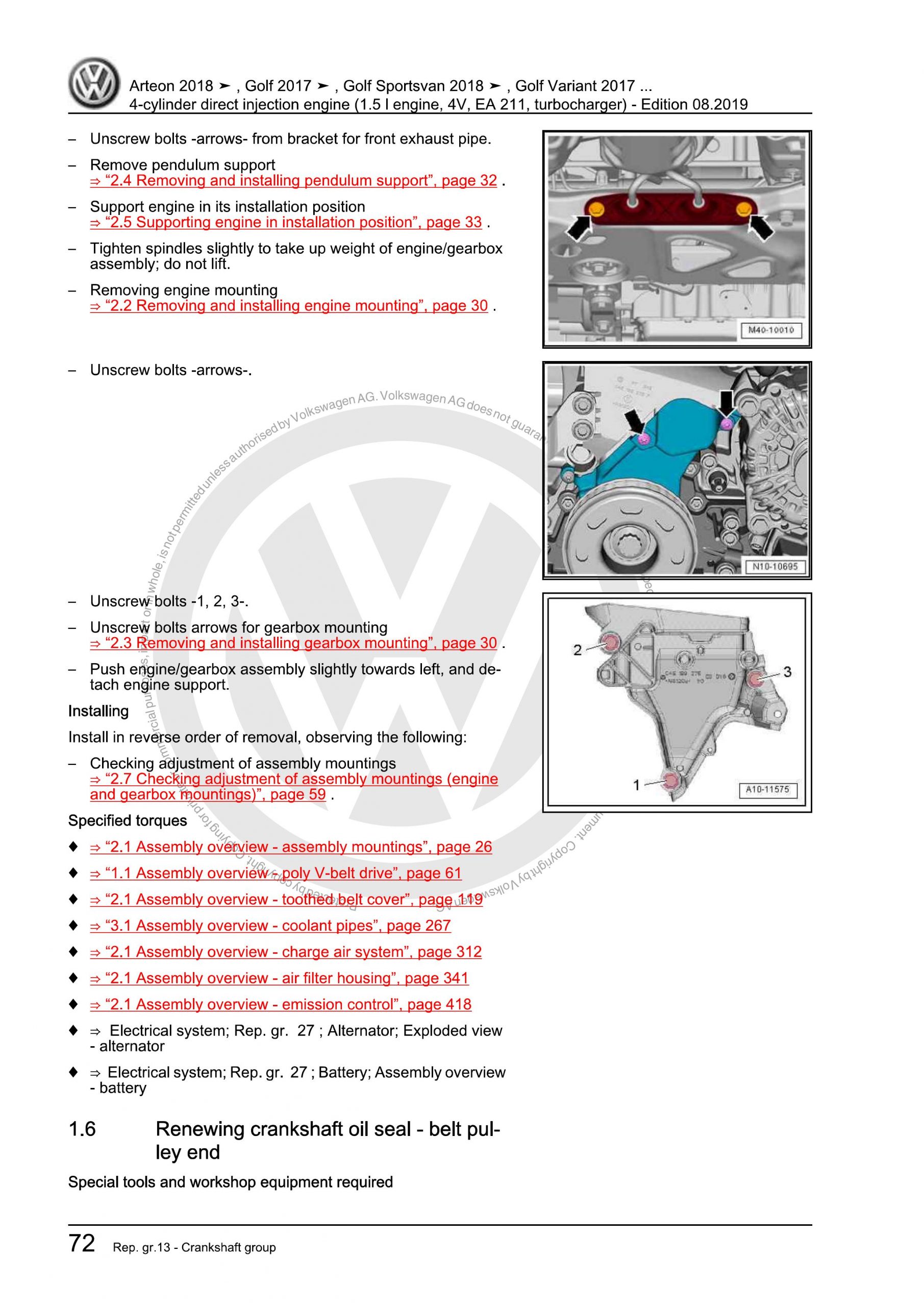
- Crankshaft group
- Cylinder head, valve gear
- Lubrication
- Cooling
- Turbocharging/supercharging
- Mixture preparation – injection
- Exhaust system
- Ignition system
Contents:
- Technical data
- Safety information
- Safety measures when working on fuel supply
- Safety measures when working on vehicles with a start/stop system
- Safety precautions when using testers and measuring instruments during a road test
- Safety precautions when working on the cooling system
- Safety precautions when working on ignition system
- Identification
- Engine number/engine data
- Repair instructions
- Rules for cleanliness
- General information
- General repair instructions
- Foreign objects in engine
- Contact corrosion
- Routing and attachment of lines
- Fitting radiator and condensers
- Checking vacuum system
- Removing and installing engine
- Removing and installing engine
- Removing engine
- Separating engine and gearbox
- Securing engine on engine and gearbox support
- Installing engine
- Assembly mountings
- Assembly overview – assembly mountings
- Removing and installing engine mounting
- Removing and installing gearbox mounting
- Removing and installing pendulum support
- Supporting engine in installation position
- Adjusting assembly mountings
- Checking adjustment of assembly mountings (engine and gearbox mountings)
- Engine cover panel
- Removing and installing engine cover
- Crankshaft group
- Cylinder block (pulley end)
- Assembly overview – poly V-belt drive
- Removing and installing poly-V belt
- Removing and installing tensioner for poly V-belt
- Removing and installing vibration damper
- Removing and installing engine support
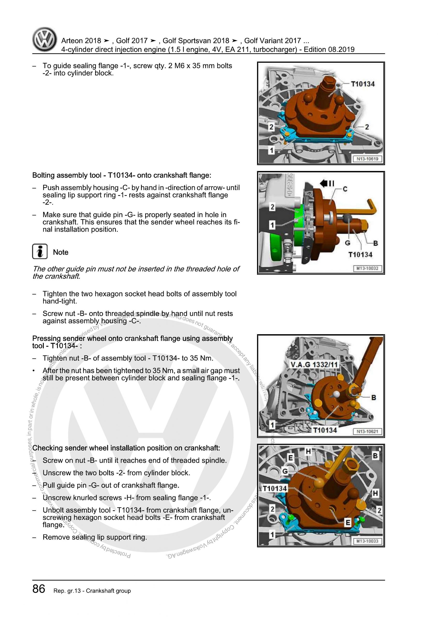
- Renewing crankshaft oil seal – belt pulley end
- Cylinder block, gearbox end
- Assembly overview – cylinder block, gearbox end
- Removing and installing flywheel
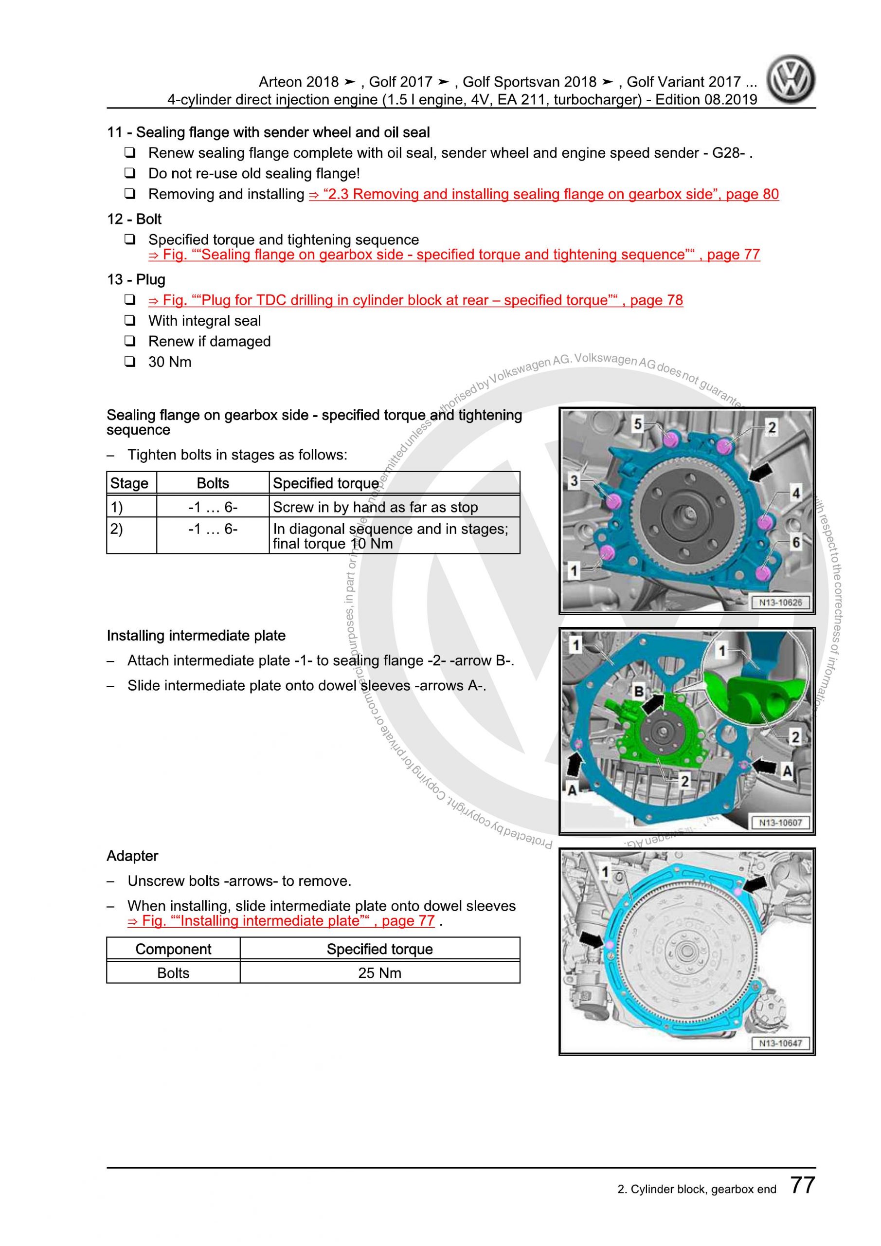
- Removing and installing sealing flange on gearbox side
- Crankshaft
- Renewing needle bearing in crankshaft
- Crankshaft dimensions
- Measuring axial clearance of crankshaft
- Pistons and conrods
- Assembly overview – pistons and conrods
- Removing and installing pistons
- Checking pistons and cylinder bores
- Separating new conrod
- Checking radial clearance of conrods
- Removing and installing oil spray jets
- Setting piston to TDC position
- Cylinder head, valve gear
- Cylinder head
- Assembly overview – cylinder head
- Assembly overview – camshaft housing
- Removing and installing cylinder head
- Removing and installing camshaft housing
- Checking compression
- Toothed belt drive
- Assembly overview – toothed belt cover
- Assembly overview – toothed belt
- Assembly overview – valve timing tool
- Removing and installing toothed belt guard
- Removing and installing toothed belt
- Preassembling and installing valve timing tool
- Checking valve timing
- Adjusting valve timing
- Removing toothed belt from camshaft
- Valve gear
- Assembly overview – valve gear
- Removing and installing camshaft oil seal
- Removing and installing camshaft adjuster
- Removing and installing cam actuators
- Removing and installing inlet camshaft control valve 1 N727
- Removing and installing exhaust camshaft control valve 1 N318
- Removing and installing valve stem seals
- Removing and installing holder for oil seal
- Inlet and exhaust valves
- Checking valve guides
- Checking valves
- Valve dimensions
- Lubrication
- Sump, oil pump
- Assembly overview – sump/oil pump
- Engine oil:
- Removing and installing sump
- Removing and installing oil pump
- Removing and installing oil level and oil temperature sender G266
- Engine oil cooler
- Assembly overview – engine oil cooler
- Removing and installing engine oil cooler
- Crankcase ventilation
- Assembly overview – crankcase breather system
- Removing and installing oil separator
- Oil filter, oil pressure switch
- Assembly overview – oil pressure switches/oil pressure control
- Removing and installing oil pressure sender G10
- Checking oil pressure and oil pressure switch
- Removing and installing oil filter housing
- Removing and installing oil pressure regulating valve N428
- Cooling
- Cooling system/coolant
- Connection diagram – coolant hoses
- Checking cooling system for leaks
- Draining and adding coolant
- Flushing cooling system
- Coolant pump, regulation of cooling system
- Assembly overview – coolant pump, thermostat
- Assembly overview – electric coolant pump
- Assembly overview – coolant temperature sender
- Removing and installing electric coolant pump
- Removing and installing coolant pump
- Removing and installing toothed belt pulley for coolant pump
- Removing and installing coolant temperature sender G62
- Removing and installing radiator outlet coolant temperature sender G83
- Removing and installing engine outlet coolant temperature sender G82
- Removing and installing engine temperature regulation module GX33
- Checking coolant pump
- Coolant pipes
- Assembly overview – coolant pipes
- Removing and installing coolant pipes
- Radiator, radiator fan
- Assembly overview – radiator/radiator fan
- Assembly overview – radiator cowl and radiator fan
- Assembly overview – radiator blind
- Removing and installing radiator
- Removing and installing water radiator for charge air cooling circuit
- Removing and installing radiator cowl
- Removing and installing radiator fan
- Removing and installing radiator blind
- Removing and installing radiator blind control motor V544
- Turbocharging/supercharging
- Turbocharger
- Assembly overview – turbocharger
- Removing and installing turbocharger
- Removing and installing connection for turbocharger
- Removing and installing charge pressure control module GX34
- Charge air system
- Assembly overview – charge air system
- Removing and installing charge air cooler
- Removing and installing charge pressure sender GX26
- Checking charge air system for leaks
- Removing and installing air pipe
- Checking charge air cooler for leaks
- Mixture preparation – injection
- Injection system
- Overview of fitting locations – injection system
- Air filter
- Assembly overview – air filter housing
- Removing and installing air filter housing
- Removing and installing air guide on lock carrier
- Intake manifold
- Assembly overview – intake manifold
- Removing and installing intake manifold
- Removing and installing throttle valve module GX3
- Cleaning throttle valve module GX3
- Injectors
- Assembly overview – fuel rail with injectors
- Removing and installing fuel rail
- Removing and installing injectors
- Cleaning injectors
- Senders and sensors
- Removing and installing intake manifold sender GX9
- Removing and installing fuel pressure sender G247
- Checking fuel pressure sender G247
- Removing and installing exhaust gas pressure sensor 1 G450
- Removing and installing air mass measurement module GX35
- High-pressure pump
- Assembly overview – high-pressure pump
- Removing and installing high-pressure pump
- Removing and installing high-pressure pipe
- Lambda probe
- Assembly overview – Lambda probe
- Removing and installing Lambda probe
- Engine control unit
- Removing and installing engine (motor) control unit J623
- Exhaust system
- Exhaust pipes and silencers
- Assembly overview – silencers
- Removing and installing silencer
- Separating exhaust pipes from silencers
- Aligning exhaust system free of stress
- Checking exhaust system for leaks
- Installation position of clamp
- Assembly overview – front exhaust pipe
- Removing and installing bracket for front exhaust pipe
- Emission control
- Assembly overview – emission control
- Removing and installing catalytic converter
- Removing and installing particulate filter
- Removing and installing exhaust flap control unit J883
- Ignition system
- Ignition system
- Assembly overview – ignition system
- Removing and installing ignition coils with output stage
- Removing and installing knock sensor 1 G61
- Removing and installing engine speed sender G28
- Removing and installing inlet camshaft position sender G1002
- Removing and installing exhaust camshaft position sender G1003




 Abrites AVDI J2534
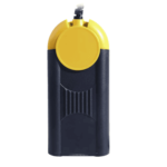 Actia Multi-Diag
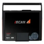 Autoland iSCAN
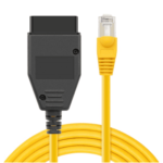 BMW ENET
 Bosch Mastertech II J2534
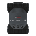 Bosch MTS 6531
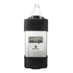 CAN CLIP RLT2002
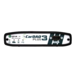 CarDAQ-Plus 3
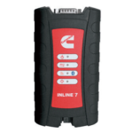 Cummins INLINE Datalink
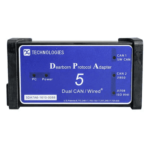 Dearborn Protocol Adapter (DPA) 5
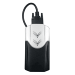 Delphi/Autocom DS150E
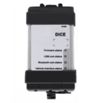 Volvo VIDA DiCE
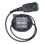 Derelek USB DIAG 3
 Electronic Data Link (EDL) 2
 Electronic Data Link (EDL) 3
 GM MDI 1
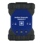 GM MDI 2
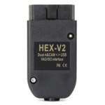 HEX-V2 VCDS VAG-COM
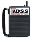 Isuzu IDSS IDS MX1
 Isuzu IDSS IDS MX2
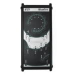 Iveco Eltrac E.A.SY. ECI
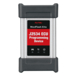 MaxiFlash Elite J2534
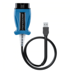 Mongoose J2534
 Nexiq USB-Link 1
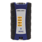 Nexiq USB-Link 2
 Nexiq USB-Link 3
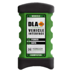 Noregon DLA+ 2.0
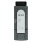 Porsche PIWIS TESTER 3 (PT3G)
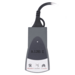 PSA LEXIA 3
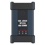 SAE J2434
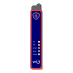 Scania VCI 3
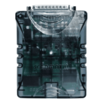 Scanmatik 2 PRO
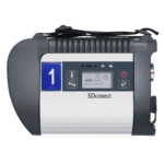 SD Connect Multiplexer
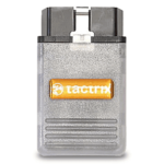 Tactrix OpenPort 2.0
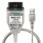 Toyota TIS Mini VCI
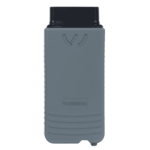 VAG ODIS VAS5054 Clone
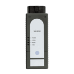 VAG ODIS VAS6154 Clone
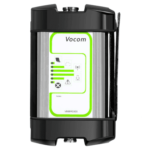 Volvo VOCOM 1
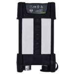 Volvo VOCOM 2




Reviews
Clear filtersThere are no reviews yet.