


 Abrites AVDI J2534
 Actia Multi-Diag
 Autoland iSCAN
 Bobcat Diagnostic Kit
 BMW ENET
 Bosch Mastertech II J2534
 Bosch MTS 6531
 CAN CLIP RLT2002
 CarDAQ-Plus 3
 Cummins INLINE Datalink
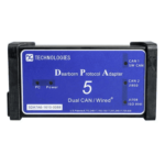 Dearborn Protocol Adapter (DPA) 5
 Delphi/Autocom DS150E
 DrewLinQ
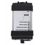 Volvo VIDA DiCE
 Derelek USB DIAG 3
 Electronic Data Link (EDL) 2
 Electronic Data Link (EDL) 3
 GM MDI 1
 GM MDI 2
 HEX-V2 VCDS VAG-COM
 Isuzu IDSS IDS MX1
 Isuzu IDSS IDS MX2
 Iveco Eltrac E.A.SY. ECI
 MaxiFlash Elite J2534
 MB Star C6
 Mongoose J2534
 Nexiq USB-Link 1
 Nexiq USB-Link 2
 Nexiq USB-Link 3
 Noregon DLA+ 2.0
 Porsche PIWIS TESTER 3 (PT3G)
 PSA LEXIA 3
 SAE J2434
 Scania VCI 3
 Scanmatik 2 PRO
 SD Connect Multiplexer
 Tactrix OpenPort 2.0
 Toyota TIS Mini VCI
 VAG ODIS VAS5054 Clone
 VAG ODIS VAS6154 Clone
 Volvo VOCOM 1
 Volvo VOCOM 2
 Xentry VCI
 Yanmar Diagnostic Interface Box (IFBOX)

")
Get the complete, updated Current Flow Diagrams V2 for your Volkswagen Golf electrical systems. This PDF delivers factory-accurate wiring schematics covering powertrain, ABS, lighting, HVAC, infotainment, comfort electronics, and more. Perfect for technicians and DIYers who need precise connector pin-outs, fuse and relay locations, and harness routing—all in one searchable document.
Delivery:
The download link will be promptly delivered to your email upon completing the checkout process.Table of Contents
Series 134 (2.0 L Petrol Engine)
- Diagram 134 / 1 – Starter & Battery Monitor Control
- Diagram 134 / 2 – Oil Level Sender & Main Relay
- Diagram 134 / 3 – ABS & Engine Control Wiring
- Diagram 134 / 4 – Injector Supply & Rail Pressure Sensor
- Diagram 134 / 5 – Ignition Coils & Spark Plugs
- Diagram 134 / 6 – Turbocharger Control & Wastegate Actuator
- Diagram 134 / 7 – Camshaft Timing Chain & Tensioner
- Diagram 134 / 8 – Cylinder Head Sensors & Actuators
- Diagram 134 / 9 – Fuel Pump Control & Low-Pressure Sensor
- Diagram 134 / 10 – Throttle Valve Module & Air Mass Meter
- Diagram 134 / 11 – Charge-Air Cooler & Diverter Valve
- Diagram 134 / 12 – Evaporative Emission Canister & Purge Valve
- Diagram 134 / 13 – Cooling Fan & Thermostat Control
- Diagram 134 / 14 – Intake Manifold Runner Control
- Diagram 134 / 15 – Knock Sensors & Camshaft Position Sensors
- Diagram 134 / 16 – Exhaust Camshaft Adjustment Valve
- Diagram 134 / 17 – Mass-Air Flow Meter & Intake Air Temperature Sender
- Diagram 134 / 18 – Fuel Injector Control & Driver Module
- Diagram 134 / 19 – Mixture Trim Valve & Fuel Pressure Regulator
- Diagram 134 / 20 – Crankshaft Position Sensor & Starter Inhibit
- Diagram 134 / 21 – Oil Pressure Sender & Engine Oil Temperature Sender
- Diagram 134 / 22 – Dual-Mass Flywheel & Starter Motor Wiring
- Diagram 134 / 23 – E-GR Valve & Secondary Air Injection
- Diagram 134 / 24 – Idle Speed Control & Throttle Actuator
- Diagram 134 / 25 – CAN-Bus Powertrain & Diagnostics Connector
- Diagram 134 / 26 – Immobiliser & Keyless Entry Receiver
- Diagram 134 / 27 – On-Board Power Supply & Earth Distribution
- Diagram 134 / 28 – Fuel Pump Control & Dash Insert
Series 127 (7-Speed DSG 0IJ)
- Diagram 127 / 1 – DSG Mechatronic Unit & CAN-Bus Interfaces
- Diagram 127 / 2 – Gear Selector Sensors & Clutch Position Senders
- Diagram 127 / 3 – Auxiliary Hydraulic Pump & Valve Assembly
- Diagram 127 / 4 – Selector Lever Module & On-Board Power Supply
- Diagram 127 / 5 – [If present, next diagram in V2…]
- Diagram 127 / 6 – [etc., through the final page]


Reviews
Clear filtersThere are no reviews yet.