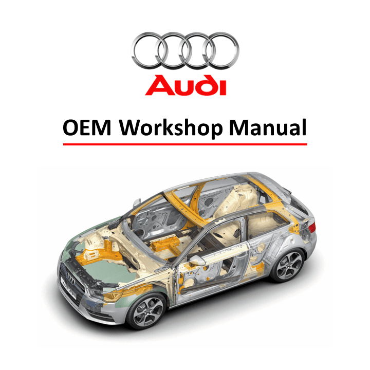
The Audi A3 (8V) Workshop Manual for servicing the 2.0-liter 4-cylinder TFSI engine (EA 888, Gen. III) is an indispensable guide for maintaining and repairing your vehicle’s engine. This manual provides detailed instructions and expert guidance for servicing the engine, including maintenance tasks, troubleshooting, and complex repairs. Ideal for professional technicians and DIY enthusiasts, this guide ensures that your Audi A3 engine operates at peak performance.
Key Features:
- Comprehensive Engine Coverage: Detailed procedures for servicing and maintaining the 2.0-liter TFSI (EA 888, Gen. III) engine in the Audi A3 (8V).
- Step-by-Step Instructions: Clear and precise steps for performing tasks such as oil changes, timing chain adjustments, valve inspections, and more.
- Troubleshooting Guidance: Expert tips for diagnosing and resolving common engine issues to ensure reliability and efficiency.
- High-Quality Diagrams: Detailed illustrations and diagrams simplify complex engine maintenance and repair processes.
- OEM Standards: Ensure all repairs and servicing meet Audi’s original specifications for performance and safety.
Format: PDF
Pages: 308
Delivery: The download link will be promptly delivered to your email upon completing the checkout process.
Covered Audi Vehicles:
- Audi A1 2011 ➤
- Audi A3 2013 ➤
- Audi A3 Limousine China 2014 ➤
- Audi Q2 2016 ➤
- Audi Q3 2012 ➤
- Audi Q3 2019 ➤
- Audi Q3 China 2013 ➤
- Audi Q3 China 2019 ➤
- Audi TT 2015 ➤
Covered Engine IDs: CWZA, DAJB, CJSA, CJSB, CJXB, CJXC, CNSB, CNTC, CHHB, CJXF, CYFB, CJXD, CJHA, CJXG, CJHB, CULB, CULC, DBRA, CHHC, DJHA, DJHB, DJJA, DBSA, DHHA, DKTB, DLRA, DNUF, DNUE, DKTA, DKTC, DKXA.
List of Workshop Manual Repair Groups:
- Technical data
- Removing and installing the engine
- Crankshaft group
- Cylinder head, valve gear
- Lubrication
- Cooling
- Turbocharging/supercharging
- Mixture preparation – injection
- Exhaust system
- Ignition system
Contents:
- Technical data
- Identification
- Engine number/engine data
- Engine versions
- Safety precautions
- Safety precautions when working on the fuel supply system
- Safety precautions when working on vehicles with start/stop system
- Safety precautions when using testers and measuring instruments during a road test
- Safety precautions when working on the cooling system
- Safety precautions when working on the exhaust system
- Safety precautions when working on the ignition system
- Repair instructions
- Identification plates
- Use of impact wrenches
- Nuts, bolts
- Rules for cleanliness
- Foreign particles in engine
- Contact corrosion
- Routing and attachment of pipes, hoses and wiring
- Installing radiators and condensers
- Checking vacuum system
- Removing and installing engine
- Removing and installing engine
- Removing engine
- Separating engine and gearbox
- Securing engine to engine and gearbox support
- Installing engine
- Assembly mountings
- Engine cover panel
- Removing and installing engine cover panel
- Crankshaft group
- Cylinder block (pulley end)
- Exploded view – cylinder block (pulley end)
- Removing and installing poly V-belt
- Removing and installing poly V-belt tensioner
- Removing and installing vibration damper
- Removing and installing bracket for ancillaries
- Removing and installing engine support
- Cylinder block (gearbox end)
- Exploded view – cylinder block (gearbox end)
- Exploded view – drive plate
- Removing and installing flywheel
- Removing and installing drive plate
- Removing and installing sealing flange (gearbox end)
- Crankshaft
- Exploded view – crankshaft
- Crankshaft dimensions
- Allocation of main bearing shells
- Renewing needle bearing in crankshaft
- Measuring axial clearance of crankshaft
- Measuring radial clearance of crankshaft
- Removing and installing sender wheel
- Balance shaft
- Exploded view – balance shaft
- Removing and installing balance shaft
- Renewing oil seal for balance shaft (inlet side)
- Pistons and conrods
- Exploded view – pistons and conrods
- Removing and installing pistons
- Removing and installing oil spray jets
- Checking pistons and cylinder bores
- Separating parts of new conrod
- Checking radial clearance of conrod bearings
- Cylinder head, valve gear
- Timing chain cover
- Exploded view – timing chain cover
- Removing and installing timing chain cover
- Renewing oil seal for vibration damper
- Chain drive
- Exploded view – camshaft timing chains
- Exploded view – drive chain for balance shaft
- Removing and installing bearing saddle
- Removing and installing camshaft timing chain
- Removing and installing drive chain for balance shaft
- Checking timing chain
- Checking valve timing
- Cylinder head
- Exploded view – cylinder head
- Removing and installing cylinder head
- Checking compression
- Valve gear
- Exploded view – valve gear
- Removing and installing camshaft
- Installing ball for slider
- Removing and installing actuators for camshaft adjustment
- Removing and installing camshaft control valve 1 N205
- Removing and installing valve stem oil seals
- Inlet and exhaust valves
- Checking valve guides
- Checking valves
- Valve dimensions
- Lubrication
- Sump/oil pump
- Exploded view – sump/oil pump
- Engine oil
- Removing and installing sump (bottom section)
- Removing and installing oil pump
- Removing and installing sump (top section)
- Removing and installing oil level and oil temperature sender G266
- Engine oil cooler
- Exploded view – engine oil cooler
- Removing and installing engine oil cooler
- Removing and installing mechanical switching valve
- Crankcase breather
- Exploded view – crankcase breather system
- Removing and installing oil separator
- Oil filter/oil pressure switches
- Exploded view – oil filter
- Exploded view – oil pressure switches/oil pressure control
- Removing and installing oil pressure switch F22
- Removing and installing oil pressure switch for reduced oil pressure F378
- Removing and installing stage 3 oil pressure switch F447
- Removing and installing valve for oil pressure control N428
- Removing and installing piston cooling jet control valve N522
- Checking oil pressure
- Cooling
- Cooling system/coolant
- Connection diagram – coolant hoses
- Checking cooling system for leaks
- Draining and filling cooling system
- Coolant pump/thermostat assembly
- Exploded view – coolant pump/thermostat
- Exploded view – electric coolant pump
- Exploded view – coolant valves
- Exploded view – coolant temperature senders
- Removing and installing electric coolant pump
- Removing and installing coolant pump
- Removing and installing toothed belt for coolant pump
- Removing and installing actuator for engine temperature regulation N493
- Removing and installing coolant temperature sender G62
- Removing and installing radiator outlet coolant temperature sender G83
- Removing and installing coolant valves
- Coolant pipes
- Radiator/radiator fans
- Turbocharging/supercharging
- Turbocharger
- Charge air system
- Exploded view – charge air system
- Exploded view – hose connections for charge air system
- Removing and installing charge air cooler
- Removing and installing charge pressure sender G31
- Checking charge air system for leaks
- Mixture preparation – injection
- 1 Injection system
- Air cleaner
- Intake manifold
- 1 Exploded view – intake manifold
- 2 Removing and installing intake manifold
- 3 Removing and installing throttle valve module GX3
- 4 Cleaning throttle valve module
- 5 Checking intake manifold change-over function
- Injectors
- Exploded view – fuel rail with injectors
- Removing and installing fuel rail
- Removing and installing injectors
- Cleaning injectors
- Senders and sensors
- Exploded view – actuator for structure-borne sound and control unit for structure-borne
- sound
- Removing and installing actuator for structure-borne sound R214
- Removing and installing control unit for structure-borne sound J869
- Removing and installing intake air temperature sender G42 / intake manifold pressure sender
- G71
- Removing and installing fuel pressure sender G247
- Checking fuel pressure sender G247
- Removing and installing fuel pressure sender for low pressure G410
- Removing and installing pressure differential sender for particulate filter G1037
- High-pressure pump
- Exploded view – high-pressure pump
- Removing and installing high-pressure pump
- Removing and installing high-pressure pipe
- Lambda probe
- Exploded view – Lambda probe
- Removing and installing Lambda probe
- Engine control unit
- Exhaust system
- Exhaust pipes/silencers
- Exploded view – silencers
- Separating exhaust pipes/silencers
- Removing and installing front silencers
- Stress-free alignment of exhaust system
- Checking exhaust system for leaks
- Emission control system
- Exhaust gas temperature control
- Exploded view – exhaust gas temperature control
- Removing and installing parts of exhaust gas temperature control
- Secondary air system
- Exploded view – secondary air system
- Removing and installing secondary air pump motor V101
- Removing and installing secondary air inlet valve N112
- Removing and installing sender 1 for secondary air pressure G609
- Ignition system
- Ignition system
- Exploded view – ignition system
- Removing and installing ignition coils
- Removing and installing knock sensor 1 G61
- Removing and installing Hall senders
- Removing and installing engine speed sender G28




 Abrites AVDI J2534
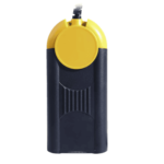 Actia Multi-Diag
 Autoland iSCAN
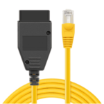 BMW ENET
 Bosch Mastertech II J2534
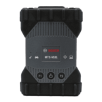 Bosch MTS 6531
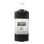 CAN CLIP RLT2002
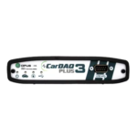 CarDAQ-Plus 3
 Cummins INLINE Datalink
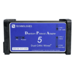 Dearborn Protocol Adapter (DPA) 5
 Delphi/Autocom DS150E
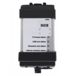 Volvo VIDA DiCE
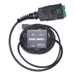 Derelek USB DIAG 3
 Electronic Data Link (EDL) 2
 Electronic Data Link (EDL) 3
 GM MDI 1
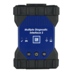 GM MDI 2
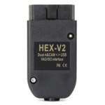 HEX-V2 VCDS VAG-COM
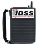 Isuzu IDSS IDS MX1
 Isuzu IDSS IDS MX2
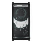 Iveco Eltrac E.A.SY. ECI
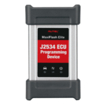 MaxiFlash Elite J2534
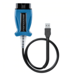 Mongoose J2534
 Nexiq USB-Link 1
 Nexiq USB-Link 2
 Nexiq USB-Link 3
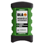 Noregon DLA+ 2.0
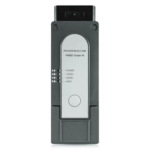 Porsche PIWIS TESTER 3 (PT3G)
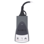 PSA LEXIA 3
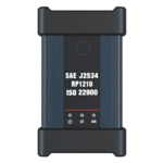 SAE J2434
 Scania VCI 3
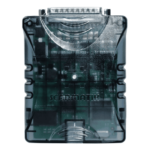 Scanmatik 2 PRO
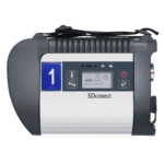 SD Connect Multiplexer
 Tactrix OpenPort 2.0
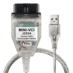 Toyota TIS Mini VCI
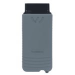 VAG ODIS VAS5054 Clone
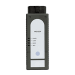 VAG ODIS VAS6154 Clone
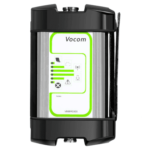 Volvo VOCOM 1
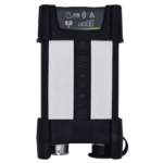 Volvo VOCOM 2







Reviews
Clear filtersThere are no reviews yet.