





Comprehensive wiring diagrams for the 2015 Audi Allroad 2.0L Turbo Quattro, covering all electrical systems including A/C, ABS, comfort electronics, and CAN-BUS communications. Ideal for diagnostic, retrofit, and repair work.
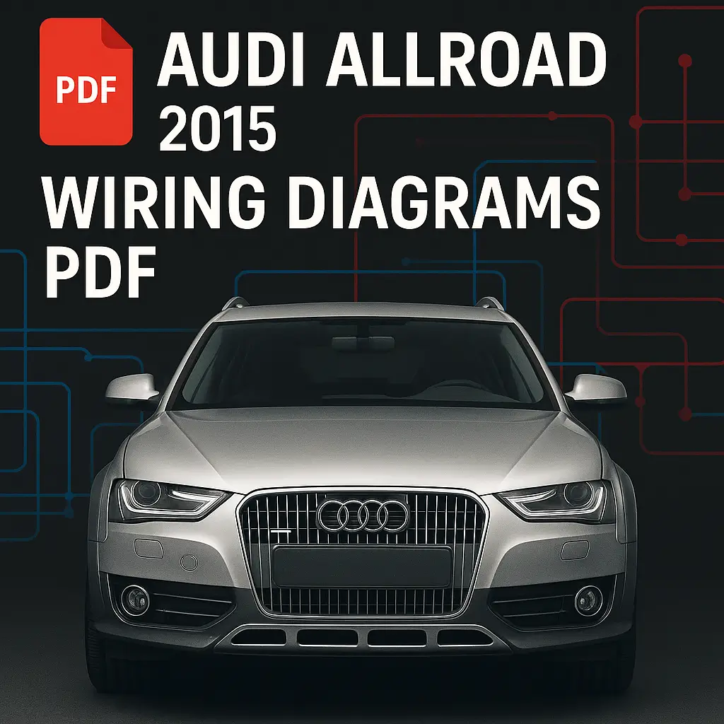

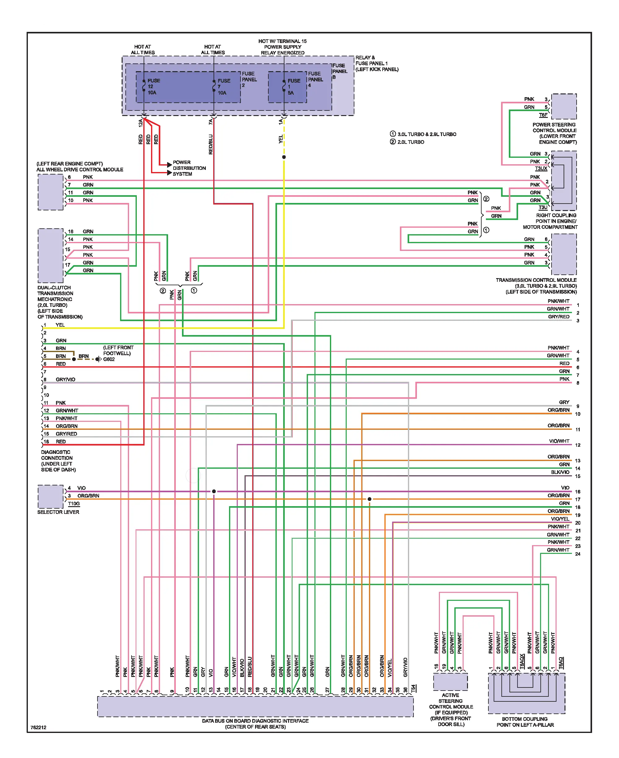
This manual includes full factory schematics for the Audi Allroad 2015 (2.0L Turbo Quattro) model. It details every circuit path, wire color, and connector pin-out for quick fault tracing and accurate electrical repair.
Automatic A/C and climate control (Basic & Comfort)
Anti-lock brake system (ABS) and brake sensors
Vehicle electrical system control modules
Comfort and anti-theft systems
Steering column and instrument cluster communication
Full CAN-BUS / LIN data line network
Connector locations and ground points
Format: PDF (searchable)
Pages: 120
Language: English
VIN Range: 2015 Allroad Prestige 2.0L Turbo
Electrical Layouts: Color-coded with component and pin references
Automatic A/C Circuit (Basic)
Fig. 1: Basic (1 of 2)
Fig. 2: Basic (2 of 2)
Automatic A/C Circuit (Comfort)
Fig. 3: Comfort (1 of 3)
Fig. 4: Comfort (2 of 3)
Fig. 5: Comfort (3 of 3)
Components and Sensors
A/C Compressor Magnetic Clutch
A/C Pressure/Temperature Sensor
Sunlight, Humidity, and Air Quality Sensors
Temperature Door Motors (Left, Right, Center, Footwell)
Coolant Fans (400W, 600W, 800W)
After-Run Coolant Pumps and Relays
Fig. 1: Anti-Lock Brake Circuit (1 of 2)
Fig. 2: Anti-Lock Brake Circuit (2 of 2)
Modules and Sensors
ABS Hydraulic Unit and Control Module
Wheel Speed Sensors (LF, RF, LR, RR)
Driving Dynamics Regulation (ASR/ESP)
Brake Lamp Switch
Active Steering and ESP Sensor Units
Steering Column Electronics Control Module
Active Steering Control Module
All-Wheel Drive Control Module
Comfort System Integration
ESP Sensor Unit
Comfort System Control Module (Sedan / Wagon)
Vehicle Electrical System Control Module
Interior Lighting and Anti-Theft Systems
Central Locking and Alarm Circuits
Power Supply and Terminal 15/30 Layouts
Engine Coolant Level and Temperature Sensors
After-Run Coolant Pump (2.0L Turbo & 3.0L SC)
Charge Air Cooling Pump
Coolant Fan Control Modules (400W–800W)
Climatronic Refrigerant Shut-Off Valves
CAN-BUS Interconnection Overview
LIN Bus and MOST Network Segments
Computer Data Line System (ORG/BRN and ORG/BLU references)
Gateway and Instrument Cluster Network
Steering Wheel Switches and Communication Lines
Seat Heating and Occupant Detection Circuits
Rear Temperature and Climate Modules
Sensor Distribution and Ground Points
Connector ID References (T17B, G639, G687, G12, etc.)
Ground Locations (e.g., under dash, left plenum)
Fuse Panel Layouts (Panel B, D, O)
No account yet?
Create an Account



Reviews
Clear filtersThere are no reviews yet.