









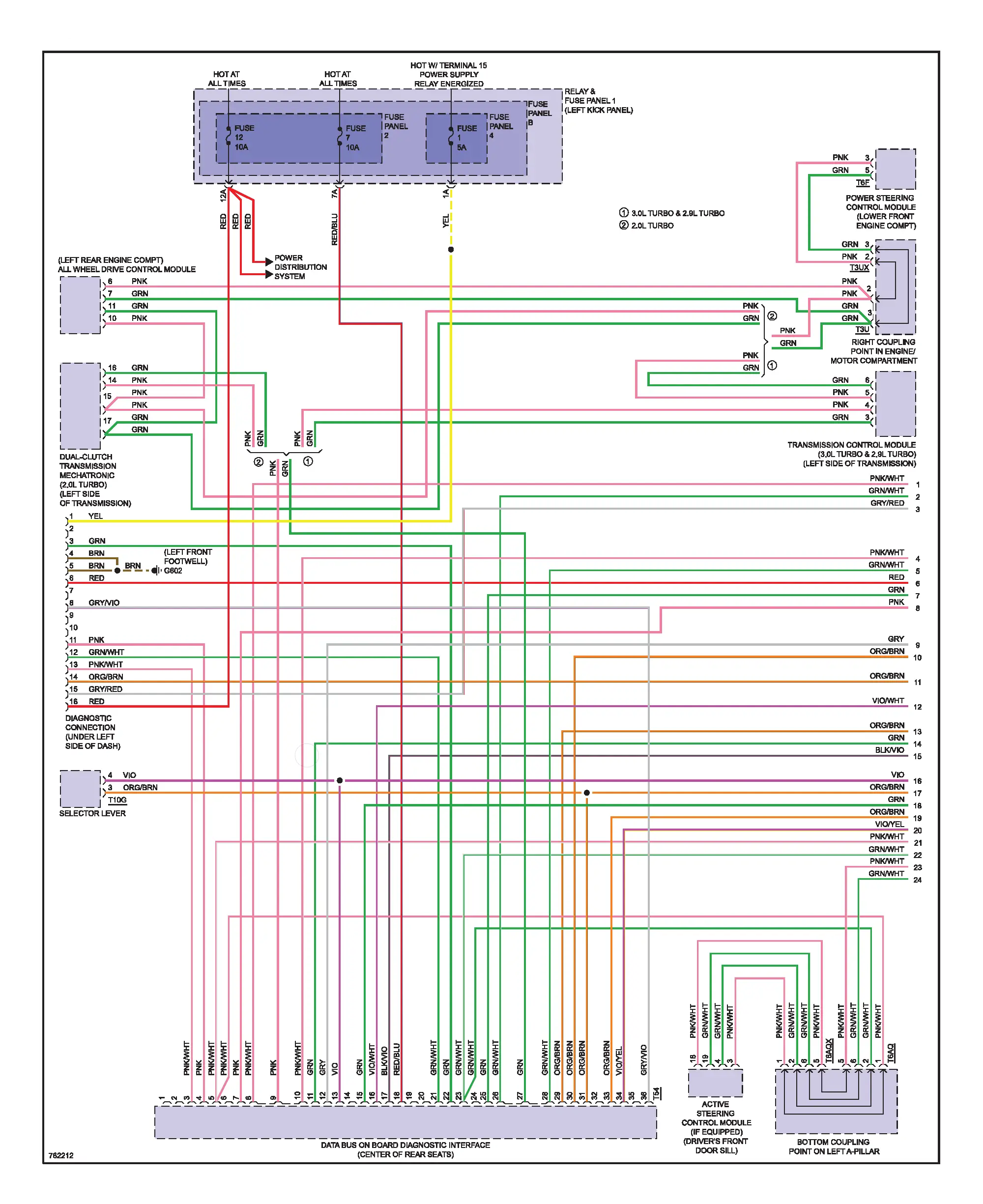
Comprehensive OEM wiring manual for the 2018 Audi Q7 covering 2.0L and 3.0L TFSI Quattro engines. Includes full electrical schematics, connector layouts, module communication maps, and color-coded circuits for professional diagnostics.

The Audi Q7 2018 Wiring Diagrams Manual provides complete OEM-level schematics for the MLB Evo platform (Typ 4M) with both 2.0L TFSI and 3.0L TFSI Quattro engines. This reference contains all electrical pathways and component-level details required for accurate troubleshooting, ECU replacement, or retrofit configuration.
Systems Covered
-
Air Conditioning System – complete automatic A/C and rear climate control circuits
-
Anti-Lock Braking (ABS/ESP) – hydraulic unit, sensors, and module wiring
-
Anti-Theft & Central Locking System – KESSY access, immobilizer, and alarm circuits
-
Body Control Modules (BCM1 / BCM2) – interior/exterior lighting, mirrors, comfort electronics
-
CAN, LIN & FlexRay Data Bus Systems – complete communication architecture linking all ECUs
-
Electronic Suspension & Ride Control – adaptive damping, control units, and sensors
-
Hybrid Auxiliary Systems – cooling pump, fan control, and auxiliary heater circuits
-
Power Distribution & Ground Points – fuse layouts, junction connectors, and terminal references
Table of Contents
-
Air Conditioning System
• Basic & Comfort A/C Circuits
• Rear Climate Control and Blower Motors
• Temperature and Pressure Sensors -
Anti-Lock Braking (ABS/ESP)
• Wheel Speed Sensors
• Hydraulic Control Unit
• Brake Booster and ABS Module -
Anti-Theft & Central Locking
• Keyless Access / Immobilizer
• Door Lock Control Units
• Alarm Siren and Trunk Module -
Body Control Modules
• BCM1 – Lighting and Power Circuits
• BCM2 – Interior, Mirrors, and Door Control
• Seat Memory and Window Systems -
Communication Networks
• CAN, LIN, FlexRay Bus Layouts
• ECU Gateway and Diagnostic Connector
• Grounding and Splice Junctions -
Electronic Suspension / Ride Control
• Damping and Level Sensor Circuits
• Control Module Power Supply -
Hybrid and Auxiliary Circuits
• Cooling Pump and Auxiliary Heater
• Fan Control Unit and Relays
Technical Highlights
-
OE color-coded circuit drawings
-
Connector terminal numbers and wire cross-sections
-
Ground and splice point index
-
CAN/FlexRay/Powertrain communication map
-
Cross-referenced component symbols for quick tracing
-
Fully compatible with ODIS, VCDS, OBDeleven, and professional diagnostic tools
File Information
-
Format: PDF (Digital Download)
-
Language: English
-
Pages: 174
⚠️ Notice
Digital delivery only — no physical media is shipped. Ensure Adobe Reader or any modern PDF viewer is installed.



Reviews
Clear filtersThere are no reviews yet.