









Product Overview
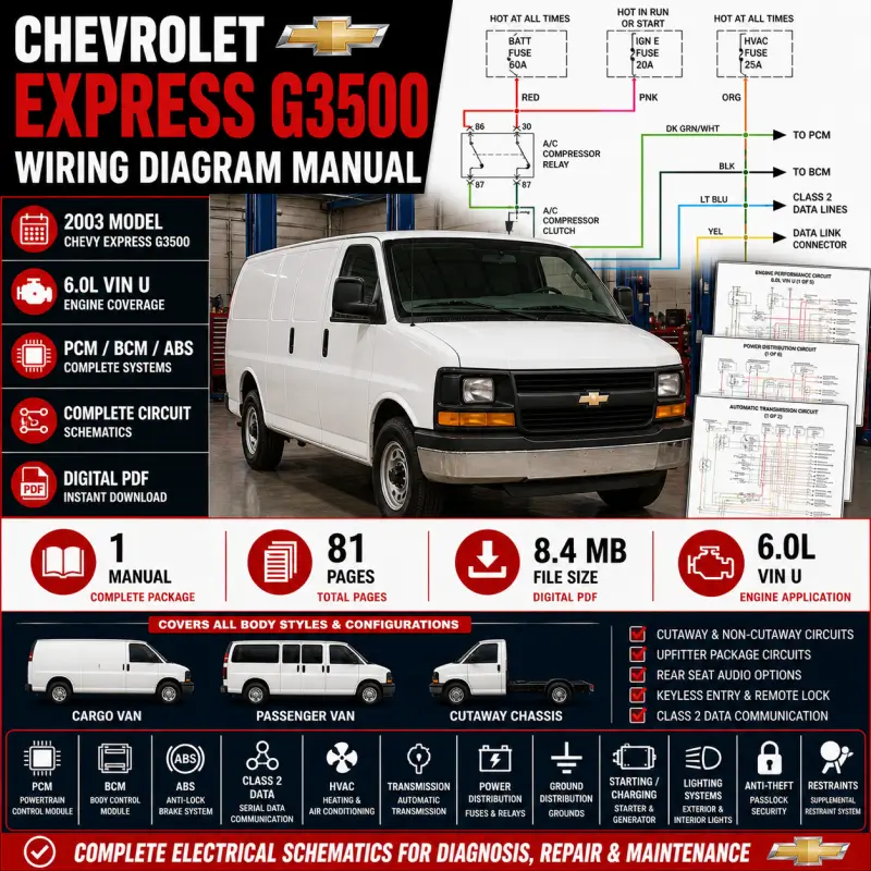
This 81-page Chevrolet Express G3500 electrical wiring manual provides detailed circuit diagrams for professional diagnostics, wiring repair, connector tracing, module testing, electrical troubleshooting and commercial-van service work.
The internal header confirms 2003 Chevrolet Chevy Express G3500, while the engine-performance section specifically identifies the 6.0L VIN U and provides a five-part engine-management circuit.
Vehicle Coverage
- Chevrolet Express G3500 2003
- 6.0L VIN U
- Cargo van, passenger van and cutaway-related circuits where applicable
- 81 pages
Engine coverage: 6.0L VIN U
Total package: 1 PDF manual / 81 pages
Approx. file size: 8.4 MB
Format: PDF
Language: English
The manual includes dedicated circuits for the 6.0L engine, automatic transmission, BCM, Class 2 data communication, upfitter configurations and both cutaway and non-cutaway exterior lighting.
Technical Highlights
- Powertrain Control Module (PCM)
- 6.0L VIN U engine-performance wiring
- Body Control Module (BCM)
- Anti-lock brake system
- Class 2 serial-data communication
- Data Link Connector
- Remote Control Door Lock Receiver
- Manual HVAC / A/C
- Cargo and passenger van HVAC circuits
- Cruise control
- Power distribution
- Ground distribution
- Starting and charging
- Automatic transmission
- Shift interlock
- Passlock anti-theft
- Cutaway chassis lighting
- Standard van exterior lighting
- Headlights
- Interior and courtesy lighting
- Upfitter-package circuits
- Instrument cluster
- Power door locks
- Power mirrors
- Power seats
- Power windows
- Radio with / without rear-seat audio
- Supplemental restraints
- Warning systems
- Wiper / washer
Table of Content
- Air Conditioning
- Compressor circuit
- Heater circuit
- Manual A/C, cargo van
- Circuit 1 of 2
- Circuit 2 of 2
- Manual A/C, passenger van
- Circuit 1 of 2
- Circuit 2 of 2
- HVAC control assembly
- A/C compressor clutch
- High and low pressure switches
- Blower and air-door controls
- Anti-Lock Brakes
- ABS circuit
- Electronic brake control
- Wheel-speed sensors
- Brake-system power and grounds
- Anti-Theft
- Passlock system
- BCM integration
- PCM communication
- Instrument-cluster security data
- Body Control Modules
- BCM circuit 1 of 2
- BCM circuit 2 of 2
- Body-system inputs and outputs
- Lighting and accessory control
- Door-related functions
- Computer Data Lines
- Class 2 serial data
- PCM communication
- BCM communication
- ABS module communication
- Instrument cluster
- Radio
- Remote Control Door Lock Receiver
- Data Link Connector
The data-line diagram explicitly connects the PCM, BCM, ABS module, instrument cluster, radio and other modules through the Class 2 network.
- Cruise Control
- Cruise-control switch
- Brake-switch inputs
- Vehicle-speed information
- PCM interface
- Defoggers
- Rear-window defogger
- Heated mirror circuits
- HVAC control interface
- Engine Performance
- 6.0L VIN U
- Engine Performance Circuit 1 of 5
- Engine Performance Circuit 2 of 5
- Engine Performance Circuit 3 of 5
- Engine Performance Circuit 4 of 5
- Engine Performance Circuit 5 of 5
- PCM power and grounds
- Fuel injection
- Ignition
- Engine sensors
- Throttle controls
- Emissions-related circuits
- Automatic-transmission interface
- 6.0L VIN U
The five dedicated engine-performance diagrams span pages 22–26 of the PDF.
- Exterior Lights
- Backup lamps
- Cutaway chassis exterior lamps
- Circuit 1 of 2
- Circuit 2 of 2
- Exterior lamps, except cutaway
- Circuit 1 of 2
- Circuit 2 of 2
- Stop / turn / tail lamps
- Marker and clearance lighting
- Ground Distribution
- Ground Distribution Circuit 1 of 4
- Ground Distribution Circuit 2 of 4
- Ground Distribution Circuit 3 of 4
- Ground Distribution Circuit 4 of 4
- Engine grounds
- Body grounds
- Lighting and accessory grounds
- Module grounding
- Headlights
- Headlight circuit
- Headlamp switching
- High / low beam circuits
- Exterior-lighting integration
- Horn
- Horn relay
- Horn switch
- Horn assembly
- Instrument Cluster
- Instrument-cluster circuit
- Gauges
- Warning indicators
- Data communication
- Interior Lights
- Courtesy lamps with upfitter package
- Courtesy lamps without upfitter package
- Circuit 1 of 2
- Circuit 2 of 2
- Instrument illumination
- Door-triggered lighting
- Interior lamp controls
- Power Distribution
- Power Distribution Circuit 1 of 6
- Power Distribution Circuit 2 of 6
- Power Distribution Circuit 3 of 6
- Power Distribution Circuit 4 of 6
- Power Distribution Circuit 5 of 6
- Power Distribution Circuit 6 of 6
- Battery feeds
- Underhood fuse block
- Body fuse block
- PCM / BCM power feeds
- HVAC and accessory feeds
- Ignition and relay circuits
Power distribution is one of the largest sections in the manual, spanning six dedicated schematics.
- Power Door Locks
- Door-lock actuators
- Door switches
- BCM control
- Remote lock interface
- Power Mirrors
- Driver mirror
- Passenger mirror
- Mirror-position switches
- Mirror motors
- Power Seats
- Driver and passenger power-seat circuits
- Seat motors
- Seat adjustment switches
- Power Windows
- Driver window
- Passenger window
- Window switches
- Window motors
- BCM-related power feeds
- Radio
- Radio with rear-seat audio
- Radio without rear-seat audio
- Speaker circuits
- Class 2 communication
- Audio-system power and grounds
- Shift Interlock
- Automatic transmission shift-lock
- Brake-pedal input
- Park / neutral position
- Shift-lock solenoid
- Starting / Charging
- Charging circuit
- Battery
- Generator
- PCM generator control
- Starting circuit
- Starter relay
- Starter motor
- Supplemental Restraints
- Supplemental Restraints Circuit 1 of 2
- Supplemental Restraints Circuit 2 of 2
- Airbag modules
- Impact sensors
- Restraint sensing
- Warning indicators
- Transmission
- Automatic Transmission Circuit 1 of 2
- Automatic Transmission Circuit 2 of 2
- PCM / transmission interface
- Transmission solenoids
- Range / position inputs
- Speed and temperature signals
- Warning Systems
- Warning-system circuit
- Instrument warnings
- Audible warning functions
- BCM / cluster interfaces
- Wiper / Washer
- Windshield wiper motor
- Wiper switch
- Washer pump
- Wiper / washer controls



Reviews
Clear filtersThere are no reviews yet.