


")
Technical Highlights
- Full ECM pinout (CM850 multi-connector architecture)
- Injector control:
- Solenoid driver circuits for cylinders 1–4 / 1–6
- Injector pass-through connector mapping
- Sensor network:
- Intake manifold pressure & temperature
- Fuel rail pressure sensor
- Barometric pressure sensor
- Engine coolant temperature
- Oil pressure switch & temperature
- Water-in-fuel sensor
- Control systems:
- Accelerator pedal (single & dual throttle configurations)
- Cruise control & PTO switches
- Engine brake control
- Torque limit switch
- Communication:
- SAE J1939 data link
- SAE J1587 data link
- Diagnostic systems:
- Red stop lamp
- Amber warning lamp
- Wait-to-start lamp
- Actuators:
- Intake air heater relay
- Fan clutch
- Starter lockout relay
- Power distribution:
- Battery supply, ignition, and fuse protection
- Optional systems:
- Aftertreatment interface connector (SCR-ready configurations)
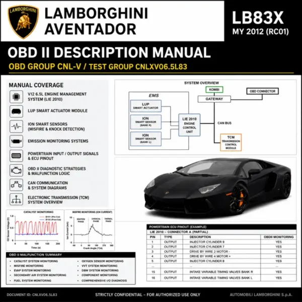
👉 The diagram on page 1 clearly shows injector driver circuits, ECM connector layouts, and detailed sensor wiring with connector mating faces, along with separation between OEM and Cummins wiring responsibilities.
Table of Content
- ECM Connector Layout (CM850)
- Injector Driver Circuits (4 & 6 Cylinder)
- Common Rail Fuel System Wiring
- Sensor Network (Pressure / Temperature / Position)
- Accelerator & Control Systems
- Diagnostic Lamps & Indicators
- Data Link Communication (J1939 / J1587)
- Actuator Control Systems
- Power Supply & Ground Distribution
File Information
- Manufacturer: Cummins
- System: ISBe2 / ISBe3 CM850 Engine Management
- ECM Type: CM850
- Fuel System: Common Rail
- Document Type: Wiring Diagram
- Bulletin: 4021670
- Format: PDF
- Pages: 1
- Content: Electrical Schematics, Pinout, Injector & Sensor Systems


Reviews
Clear filtersThere are no reviews yet.