







Vehicle Coverage
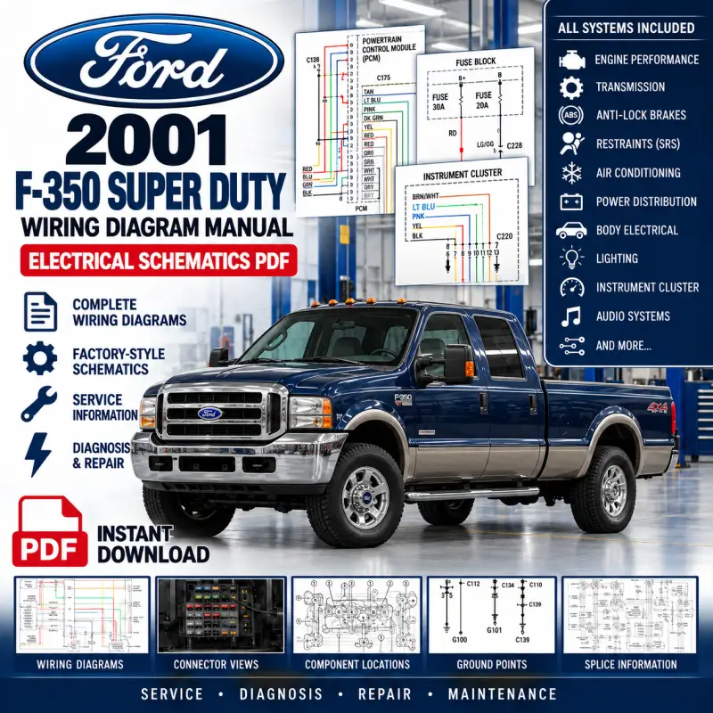
- Model: Ford F-350 Super Duty
- Year: 2001
- Engine circuits included: 5.4L, 6.8L, 6.8L Bi-Fuel & 7.3L DI Turbo Diesel
- Manual: 116-page system wiring-diagram PDF
- File size: approximately 5.81 MB
- Language: English
Circuit selection varies by engine, transmission, cab/body style and installed equipment. Match the relevant diagram to the vehicle configuration.
Technical Highlights
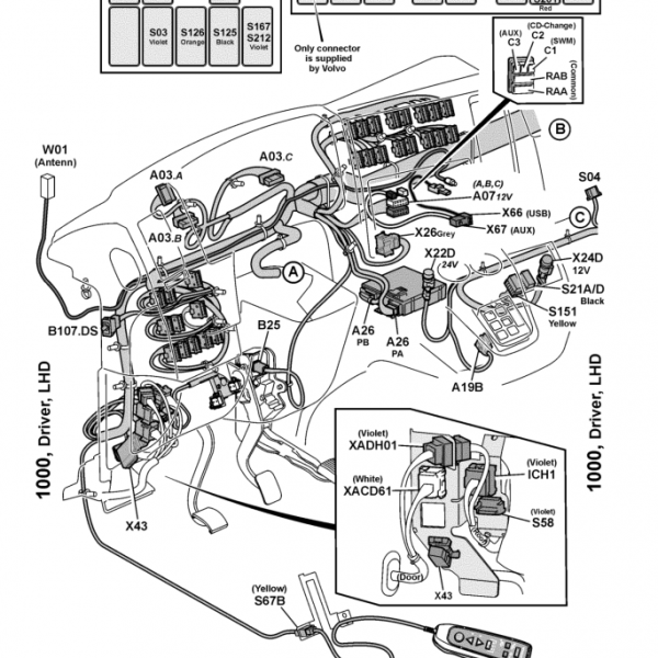
Use these Ford F-350 Super Duty wiring diagrams 2001 to trace electrical circuits and identify connections across the systems included in this manual. The PDF contains system schematics with wiring colours, component labels, connector references and power/ground paths.
- Engine-management and drivetrain electrical circuits.
- Power distribution, ground distribution, starting and charging wiring.
- Lighting, instrumentation, power accessories and warning systems.
- Equipment-specific variants identified in the contents below.
Table of Contents
Original section headings and diagram captions, in PDF order. Page numbers refer to the supplied PDF.
AIR CONDITIONING (p. 1)
- Fig. 1: Heater Circuit — p. 2
- 5.4L — p. 3
- Fig. 2: 5.4L, Manual A/C Circuit — p. 4
- 6.8L — p. 5
- Fig. 3: 6.8L, Manual A/C Circuit — p. 6
- 7.3L DI TURBO DIESEL — p. 7
- Fig. 4: 7.3L DI Turbo Diesel, Manual A/C Circuit — p. 8
ANTI-LOCK BRAKES (p. 9)
- Fig. 5: All-Wheel ABS Circuit — p. 10
- Fig. 6: Rear Wheel ABS Circuit — p. 11
BODY CONTROL MODULES (p. 12)
- Fig. 7: Body Control Modules Circuit (1 of 2) — p. 13
- Fig. 8: Body Control Modules Circuit (2 of 2) — p. 14
COMPUTER DATA LINES (p. 15)
- Fig. 9: Computer Data Lines Circuit — p. 16
CRUISE CONTROL 5.4L (p. 17)
- Fig. 10: 5.4L, Cruise Control Circuit — p. 18
- 6.8L — p. 19
- Fig. 11: 6.8L, Cruise Control Circuit — p. 20
- 7.3L DI TURBO DIESEL — p. 21
- Fig. 12: 7.3L DI Turbo Diesel, Cruise Control Circuit — p. 22
ENGINE PERFORMANCE 5.4L (p. 23)
- Fig. 13: 5.4L, Engine Performance Circuit (1 of 4) — p. 24
- Fig. 14: 5.4L, Engine Performance Circuit (2 of 4) — p. 25
- Fig. 15: 5.4L, Engine Performance Circuit (3 of 4) — p. 26
- Fig. 16: 5.4L, Engine Performance Circuit (4 of 4) — p. 27
- 6.8L — p. 28
- Fig. 17: 6.8L, Engine Performance Circuit (1 of 4) — p. 29
- Fig. 18: 6.8L, Engine Performance Circuit (2 of 4) — p. 30
- Fig. 19: 6.8L, Engine Performance Circuit (3 of 4) — p. 31
- Fig. 20: 6.8L, Engine Performance Circuit (4 of 4) — p. 32
- 6.8L BI-FUEL — p. 33
- Fig. 21: 6.8L Bi-Fuel, Engine Performance Circuit (1 of 6) — p. 34
- Fig. 22: 6.8L Bi-Fuel, Engine Performance Circuit (2 of 6) — p. 35
- Fig. 23: 6.8L Bi-Fuel, Engine Performance Circuit (3 of 6) — p. 36
- Fig. 24: 6.8L Bi-Fuel, Engine Performance Circuit (4 of 6) — p. 37
- Fig. 25: 6.8L Bi-Fuel, Engine Performance Circuit (5 of 6) — p. 38
- Fig. 26: 6.8L Bi-Fuel, Engine Performance Circuit (6 of 6) — p. 39
- 7.3L DI TURBO DIESEL — p. 40
- Fig. 27: 7.3L DI Turbo Diesel, Engine Performance Circuit, California (1 of 4) — p. 41
- Fig. 28: 7.3L DI Turbo Diesel, Engine Performance Circuit, California (2 of 4) — p. 42
- Fig. 29: 7.3L DI Turbo Diesel, Engine Performance Circuit, California (3 of 4) — p. 43
- Fig. 30: 7.3L DI Turbo Diesel, Engine Performance Circuit, California (4 of 4) — p. 44
- Fig. 31: 7.3L DI Turbo Diesel, Engine Performance Circuit, Federal (1 of 4) — p. 45
- Fig. 32: 7.3L DI Turbo Diesel, Engine Performance Circuit, Federal (2 of 4) — p. 46
- Fig. 33: 7.3L DI Turbo Diesel, Engine Performance Circuit, Federal (3 of 4) — p. 47
- Fig. 34: 7.3L DI Turbo Diesel, Engine Performance Circuit, Federal (4 of 4) — p. 48
EXTERIOR LIGHTS (p. 49)
- Fig. 35: Back-up Lamps Circuit — p. 50
- Fig. 36: Exterior Lamps Circuit (1 of 2) — p. 51
- Fig. 37: Exterior Lamps Circuit (2 of 2) — p. 52
GROUND DISTRIBUTION (p. 53)
- Fig. 38: Ground Distribution Circuit (1 of 3) — p. 54
- Fig. 39: Ground Distribution Circuit (2 of 3) — p. 55
- Fig. 40: Ground Distribution Circuit (3 of 3) — p. 56
HEADLIGHTS (p. 57)
- Fig. 41: Headlights Circuit, W/ DRL — p. 58
- Fig. 42: Headlights Circuit, W/O DRL — p. 59
HORN (p. 60)
- Fig. 43: Horn Circuit — p. 61
INSTRUMENT CLUSTER (p. 62)
- Fig. 44: Instrument Cluster Circuit — p. 63
- Fig. 45: Overhead Console Circuit — p. 64
INTERIOR LIGHTS (p. 65)
- Fig. 46: Courtesy Lamps Circuit — p. 66
- Fig. 47: Instrument Illumination Circuit — p. 67
POWER DISTRIBUTION (p. 68)
- Fig. 48: Power Distribution Circuit (1 of 4) — p. 69
- Fig. 49: Power Distribution Circuit (2 of 4) — p. 70
- Fig. 50: Power Distribution Circuit (3 of 4) — p. 71
- Fig. 51: Power Distribution Circuit (4 of 4) — p. 72
POWER DOOR LOCKS (p. 73)
- Fig. 52: Power Door Locks Circuit, W/ Remote/Keyless Entry Except Crew Cab — p. 74
- Fig. 53: Power Door Locks Circuit, W/ Remote/Keyless Entry-Crew Cab — p. 75
- Fig. 54: Power Door Locks Circuit, W/O Remote/Keyless Entry Except Crew Cab — p. 76
- Fig. 55: Power Door Locks Circuit, W/O Remote/Keyless Entry-Crew Cab — p. 77
POWER MIRRORS (p. 78)
- Fig. 56: Power Mirrors Circuit — p. 79
POWER SEATS (p. 80)
- Fig. 57: 6-Way Power Seat Circuit — p. 81
- Fig. 58: Adjustable Pedal Circuit — p. 82
- Fig. 59: Heated Seats Circuit — p. 83
POWER WINDOWS (p. 84)
- Fig. 60: Power Windows Circuit, Crew Cab — p. 85
- Fig. 61: Power Windows Circuit, Except Crew Cab — p. 86
RADIO (p. 87)
- Fig. 62: Radio Circuit — p. 88
SHIFT INTERLOCK (p. 89)
- Fig. 63: Shift Interlock Circuit — p. 90
STARTING/CHARGING (p. 91)
- Fig. 64: Starting Circuit — p. 92
- 5.4L — p. 93
- Fig. 65: 5.4L, Charging Circuit — p. 94
- 6.8L — p. 95
- Fig. 66: 6.8L, Charging Circuit — p. 96
- 7.3L DIESEL — p. 97
- Fig. 67: 7.3L Diesel, Charging Circuit, W/ Dual Generators — p. 98
- Fig. 68: 7.3L Diesel, Charging Circuit, W/O Dual Generators — p. 99
SUPPLEMENTAL RESTRAINTS (p. 100)
- Fig. 69: Supplemental Restraints Circuit, Early Production — p. 101
- Fig. 70: Supplemental Restraints Circuit, Late Production — p. 102
TRANSMISSION (p. 103)
- Fig. 71: 4WD Circuit — p. 104
- 5.4L — p. 105
- Fig. 72: 5.4L, A/T Circuit — p. 106
- 6.8L — p. 107
- Fig. 73: 6.8L, A/T Circuit — p. 108
- 6.8L BI-FUEL — p. 109
- Fig. 74: 6.8L Bi-Fuel, A/T Circuit — p. 110
- 7.3L DIESEL — p. 111
- Fig. 75: 7.3L Diesel, A/T Circuit — p. 112
WARNING SYSTEMS (p. 113)
- Fig. 76: Warning Systems Circuit — p. 114
WIPER/WASHER (p. 115)
- Fig. 77: Wiper/Washer Circuit — p. 116
File Details
- Files: 1 PDF wiring manual
- Pages: 116
- File size: approximately 5.81 MB
- Year: 2001
- Model: Ford F-350 Super Duty
- Language: English
- Delivery: Digital PDF download after purchase
Reviews
Clear filtersThere are no reviews yet.