







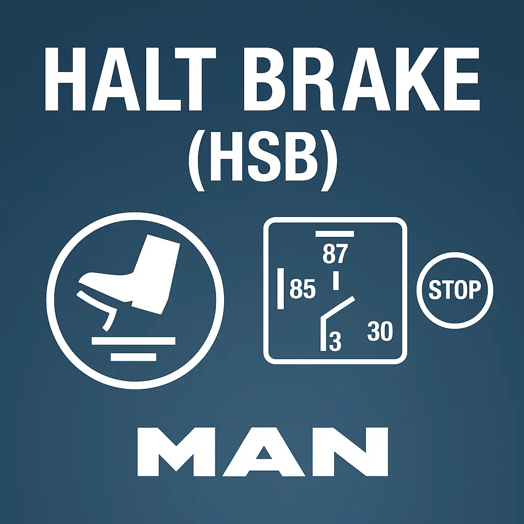

This official 2-page schematic from MAN Truck & Bus SE (Werk München) details the wiring logic for the Haltestellenbremse (HSB) or Halt Brake System, designed for MAN TG3 TGX/TGS Euro 6d vehicles. This system is typically installed in public service or waste collection trucks, enabling a controlled stop function at frequent stops.
🛠️ Coverage includes:
-
Switches & Control:
-
S312.1 / S312.2 – Halt brake switch (SP008)
-
S652.1 – ASF application switch (Comfort Variant)
-
SP008 – Assigned to EIO1 or CVM module
-
-
Relays & Fusing:
-
K359.1, K360.1, K361.1 – HSB control relays
-
F238.1 (FP002) – HSB system fuse
-
Relay sockets: X4455.1 / X4455.2
-
-
Control Units & Pressure Detection:
-
A100.1 – Central electrical unit
-
A402.1 / A402.2 – EBS control unit
-
B230.1 / B230.2 – Pressure switch for parking brake status (B472)
-
-
Connectivity & Variants:
-
CAN lines: CAN_1939_HI / LO
-
Multiple variant support:
-
Standard: With K361 relay
-
Comfort (ASF): Without K361, uses simplified control logic
-
-
Chassis interfaces: X6408, X203, X6301, X6396.1, XV805.1
-
Perfect for:
-
Brake function diagnostics in stop-and-go commercial vehicles
-
Configuring or retrofitting HSB systems in refuse vehicles
-
CAN signal tracing between brake pressure switches and EBS logic
-
Compliance and functionality checks of the hold-brake loop



Reviews
Clear filtersThere are no reviews yet.