


 Abrites AVDI J2534
 Actia Multi-Diag
 Autoland iSCAN
 Bobcat Diagnostic Kit
 BMW ENET
 Bosch Mastertech II J2534
 Bosch MTS 6531
 CAN CLIP RLT2002
 CarDAQ-Plus 3
 Cummins INLINE Datalink
 Dearborn Protocol Adapter (DPA) 5
 Delphi/Autocom DS150E
 DrewLinQ
 Volvo VIDA DiCE
 Derelek USB DIAG 3
 Electronic Data Link (EDL) 2
 Electronic Data Link (EDL) 3
 GM MDI 1
 GM MDI 2
 HEX-V2 VCDS VAG-COM
 Isuzu IDSS IDS MX1
 Isuzu IDSS IDS MX2
 Iveco Eltrac E.A.SY. ECI
 MaxiFlash Elite J2534
 MB Star C6
 Mongoose J2534
 Nexiq USB-Link 1
 Nexiq USB-Link 2
 Nexiq USB-Link 3
 Noregon DLA+ 2.0
 Porsche PIWIS TESTER 3 (PT3G)
 PSA LEXIA 3
 SAE J2434
 Scania VCI 3
 Scanmatik 2 PRO
 SD Connect Multiplexer
 Tactrix OpenPort 2.0
 Toyota TIS Mini VCI
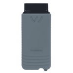 VAG ODIS VAS5054 Clone
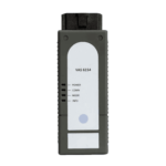 VAG ODIS VAS6154 Clone
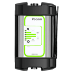 Volvo VOCOM 1
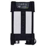 Volvo VOCOM 2
 Xentry VCI
 Yanmar Diagnostic Interface Box (IFBOX)

")
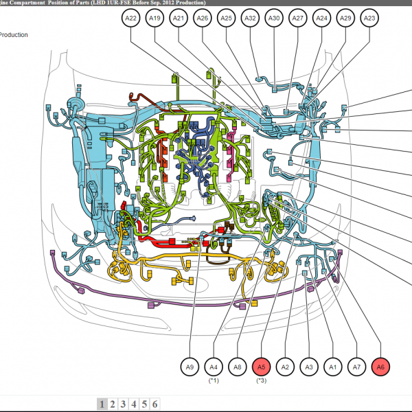
This official OEM schematic outlines the Immobilizer System (Wegfahrsperre) for MAN TG3 TGX/TGS Euro 6d trucks, sourced from MAN Truck & Bus SE – Werk München, Q4 2020 release. It maps the control logic, CAN integration, and transponder pulse communication between the immobilizer unit and the Central Vehicle Module (CVM).
🔒 System Components:
A477.1 – Immobilizer control unit (Elektronik Wegfahrsperre)
A1363.2 (AP025) – CVM (Central Vehicle Module)
A/1 – Data (transponder pulse signal)
A/2 – Terminal 15 (Ignition power)
A/3 – Terminal 31 (Ground)
CAN Bus:
A/13 (I-CAN)
A/14 (CAN 5 Low – CVM)
A/63 (CAN 5 High – CVM)
⚡ Connections are routed through:
SYS_groundNet
SYS_electricalPowerSupply
Frame harness connector X6395.1
Zentralelektrik interface: A100.1 / X2
🛡️ This diagram is ideal for:
Diagnosing vehicle no-start conditions due to immobilizer faults
Troubleshooting CAN dropouts between CVM and immobilizer
Retrofits or ECU swaps requiring immobilizer pairing
Understanding transponder signal routing and key security logic


Reviews
Clear filtersThere are no reviews yet.