









This technical wiring manual contains the complete electrical schematics for the auxiliary power socket and power take-off (PTO) systems used in MAN TG3 trucks.
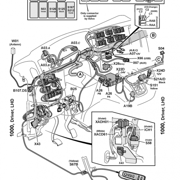
The diagrams include the full control architecture for the inverter power supply circuits, PTO activation controls, gearbox interface wiring, CAN communication networks, fuse protection and electrical routing.
All circuits include connector identifiers, system references and grounding architecture required for professional diagnostics, repair, retrofit installation or PTO troubleshooting.
Power Socket and Inverter System Components
-
Power inverter transformer (24V to 230V supply)
-
Auxiliary power socket circuits
-
Electrical supply connectors
-
Control interface wiring
These components provide onboard auxiliary AC power and socket supply through the vehicle electrical system.
Power Take-Off Control Components
-
PTO control switches
-
PTO solenoid activation wiring
-
Gearbox PTO interface connections
-
PTO enable control circuits
These circuits control mechanical PTO activation and auxiliary hydraulic or mechanical equipment.
CAN Bus and Electronic Communication
-
Vehicle CAN communication network integration
-
Control module interface wiring
-
Signal routing between PTO controls and vehicle systems
The PTO and inverter systems communicate with vehicle electronics through the CAN architecture for safe activation and monitoring.
Electrical Supply and Fuse Protection
-
Central electrical system supply routing
-
Fuse-protected auxiliary power circuits
-
PTO electrical feed connections
-
Ground network references
These protected circuits ensure stable power distribution for both inverter and PTO operation.
Wiring Harness Interfaces
-
Cab-frame harness connectors
-
Frame electrical routing connectors
-
Auxiliary interface connectors
-
System cut-off connection points
These harness references allow full diagnostic tracing of PTO and auxiliary power electrical systems.
Diagnostic Use Cases
-
PTO not engaging
-
inverter power socket not working
-
auxiliary power failure
-
PTO control switch malfunction
-
CAN communication PTO errors
-
fuse or electrical routing faults
-
inverter supply instability
Compatible Vehicles
-
TGX
-
TGS
-
TGM
-
TGL
MAN TG3 platform trucks equipped with PTO system and auxiliary power socket or inverter option.
Technical Highlights
-
Complete OEM PTO and auxiliary power wiring diagrams
-
Inverter electrical architecture included
-
PTO solenoid control circuits included
-
CAN bus communication integration shown
-
Fuse protection and supply routing included
-
Full harness routing references included
Table of Content
Power Socket System
-
Inverter transformer circuits
-
Auxiliary socket wiring
-
Power supply routing
Power Take-Off System
-
PTO activation switches
-
PTO solenoid wiring
-
Gearbox PTO interface
Electronic Communication
-
CAN network integration
-
Control module signal routing
Electrical Protection
-
Fuse-protected auxiliary circuits
-
Central electrical system connections
-
Ground network references
Wiring Harness Interfaces
-
Cab-frame connectors
-
Frame routing connectors
-
Auxiliary connection points

Reviews
Clear filtersThere are no reviews yet.