







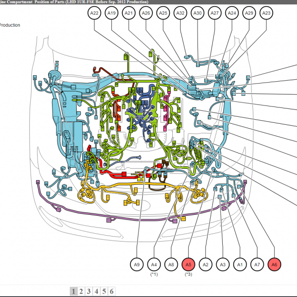
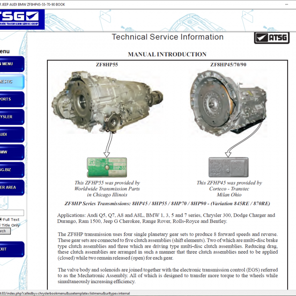
This technical wiring manual contains the complete electrical schematics for the wear-free braking systems used in MAN TG3 trucks including hydraulic retarder systems, engine brake EVB control and integrated braking electronics.
The diagrams include the full control architecture for retarder control units, steering column retarder request input, engine brake solenoid valves, pressure and temperature monitoring sensors, CAN communication routing and electrical supply connections.
All circuits include connector identifiers, system references and grounding architecture required for professional diagnostics, repair or braking system troubleshooting.
Retarder Control System Components
-
Retarder control unit
-
Retarder valve block / PriTarder assembly
-
Proportional valve retarder
-
Enable valve retarder
-
Accumulator valve
-
Retarder housing pressure sensor
-
Retarder coolant temperature sensor
-
Retarder oil temperature sensor
These components form the hydraulic wear-free braking system and monitoring architecture.
Engine Brake (EVB) Components
-
Engine brake solenoid valves (EVB)
-
EVB control module
-
Back pressure flap switch
-
Engine ECU interface wiring
These circuits manage engine compression braking and exhaust brake functionality.
Driver Control Inputs
-
Steering column retarder switch
-
BrakeMatic user request via instrument cluster
-
Retarder request signal routing
-
+5V sensor supply lines for stalk switch
These signals provide driver-controlled activation of wear-free braking systems.
CAN Bus and Electronic Communication
-
I-CAN communication with CVM
-
M-CAN routing to engine ECU
-
G-CAN communication with retarder ECU
-
Vehicle braking system signal integration
The braking electronics communicate with vehicle control modules for coordinated braking logic and monitoring.
Electrical Supply and Ground Routing
-
Terminal +15 ignition supply
-
Terminal +30 permanent supply
-
Fuse-protected retarder circuits
-
Central electrical system routing
-
SYS_groundNet grounding references
These protected circuits ensure stable electrical operation of braking electronics and sensors.
Wiring Harness Interfaces
-
Cab-frame connectors
-
Steering column harness connectors
-
Frame harness separation connectors
-
Gearbox installation wiring interfaces
-
Retarder assembly connectors
These harness references allow full diagnostic tracing of braking electrical circuits and hydraulic monitoring wiring paths.
Diagnostic Use Cases
-
retarder not engaging
-
engine brake not responding
-
EVB solenoid faults
-
pressure sensor errors
-
temperature sensor signal faults
-
CAN communication braking errors
-
driver retarder switch not detected
Compatible Vehicles
-
TGX
-
TGS
-
TGM
-
TGL
MAN TG3 platform trucks equipped with hydraulic retarder, PriTarder or engine brake EVB systems.
Technical Highlights
-
Complete OEM wear-free braking wiring diagrams
-
Retarder ECU and hydraulic valve block circuits included
-
Engine brake EVB control wiring included
-
Pressure and temperature sensor circuits included
-
Multi-CAN communication routing shown
-
Full harness routing references included
Table of Content
Retarder System
-
Retarder ECU wiring
-
Hydraulic valve block circuits
-
Pressure and temperature sensors
Engine Brake System
-
EVB solenoid wiring
-
Back pressure flap switch
-
Engine ECU interfaces
Driver Inputs
-
Steering column retarder switch
-
BrakeMatic activation signals
Communication Networks
-
I-CAN routing
-
M-CAN routing
-
G-CAN routing
Electrical Infrastructure
-
Central electrical system supply
-
Fuse protection routing
-
Ground network references
Wiring Harness Interfaces
-
Steering column connectors
-
Frame connectors
-
Gearbox installation interfaces
-
Retarder assembly wiring



Reviews
Clear filtersThere are no reviews yet.