







Overview
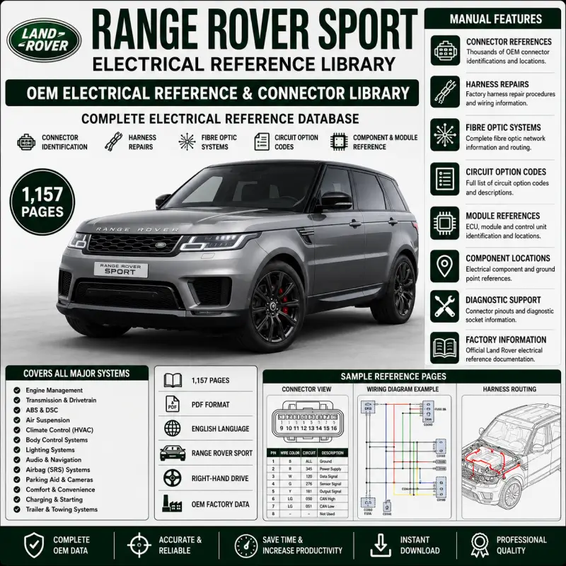
This Range Rover Sport Electrical Wiring Diagrams Manual provides factory-style circuit schematics for major electrical, electronic, drivetrain, chassis, safety, comfort and infotainment systems.
The 254-page manual includes detailed wiring paths, connector and pin references, fuse and relay circuits, module communications, wire colour codes, ground points and component interconnections. It is intended for qualified automotive electricians and should be used alongside the workshop manual and Electrical Reference Library for connector details.
Key benefits include:
- Complete colour-coded electrical schematics
- Connector numbers and pin references
- Fuse, relay and power-distribution circuits
- Ground-point identification
- Petrol and diesel engine-management diagrams
- Automatic transmission and transfer-box wiring
- Air suspension and Dynamic Response circuits
- Terrain Response and rear differential electronics
- CAN bus and diagnostic communication networks
- Climate control, lighting and interior electronics
Ideal for Land Rover specialists, automotive electricians, diagnostic technicians, restoration workshops and advanced electrical troubleshooting.
Vehicle Coverage
- Vehicle: Range Rover Sport
- Document type: Electrical Wiring Diagrams
- Drive systems: Four-wheel drive
- Engine coverage: Petrol and diesel configurations
- Steering configurations: Left-hand drive and right-hand drive circuits
- Model-year coverage: Not explicitly stated on the visible title or contents pages
The manual title confirms Range Rover Sport electrical wiring coverage, but no exact production years are printed in the reviewed title section.
Technical Coverage
- Tire Pressure Monitoring System
- Air Suspension
- Terrain Response
- Dynamic Response
- Rear Electronic Differential
- Electric Parking Brake
- ABS and Stability Control
- Steering Column Electronics
- Engine Cooling
- Starting and Charging
- Petrol and Diesel Engine Controls
- Automatic Transmission
- Transfer Box
- Fuel Tank and Fuel Lines
- Cruise Control
- Climate Control
- Auxiliary Climate Control
- Instrument Cluster
- Parking Aid
- Battery and Ground Distribution
- Audio, Navigation and Entertainment
- Exterior and Interior Lighting
- CAN Bus Networks
- Anti-Theft and Immobiliser Systems
- Mirrors, Seats and Memory
- Windows and Door Locks
- Wipers and Washers
- Roof Opening Panel
- Supplemental Restraint System
Wiring and Diagnostic Information
The diagrams explain connector numbering, wire colours, circuit continuation symbols and ground-point identification. Power and ground distribution circuits are placed under the battery, mounting and cables section, while circuit sheet numbering indicates each sheet’s position within a multi-page circuit.
The manual also includes:
- Component identification codes
- Connector pin numbers
- Harness splice references
- Wire cross-sectional sizes
- Wire colour tracers
- Circuit sheet continuation references
- Male and female connector symbols
- CAN High and CAN Low communication lines
- Module power, ignition and ground circuits
Table of Contents
- Abbreviations
- Using This Publication
- Health and Safety
- Using This Publication
- Test Equipment and Other Reference Material
- Battery Disconnection and Reconnection
- Fault Diagnosis
- Harness Repair
- Section Numbering
- Circuit Sheet Numbering
- Understanding the Circuit Diagrams
- Components
- Connectors
- Wire Length
- Line Types
- Ground Points
- Colour Codes
- Wheels and Tires
- Tire Pressure Monitoring System
- Vehicle Dynamic Suspension
- Air Suspension
- Ride and Handling Optimization
- Terrain Response
- Dynamic Response
- Rear Drive Axle and Differential
- Parking Brake and Actuation
- Anti-Lock Control
- Steering Angle Sensor
- Steering Column
- Clock Spring
- Adjustable Steering Column Memory
- Engine Cooling
- Petrol V8
- Cooling Fans – Diesel
- Starting System
- Ignition Switch
- Electronic Engine Controls
- Petrol V8
- Diesel 3.0L
- Diesel V6
- Automatic Transmission
- Petrol
- Diesel
- Four-Wheel Drive Systems
- Transfer Box – Diesel
- Transfer Box – Petrol
- Fuel Tank and Fuel Lines
- Speed Control
- Climate Control
- Automatic Climate Control
- Auxiliary Climate Control
- Rear Window Heater
- Windshield Heater
- Fuel-Fired Booster Heater
- Cool Box
- Instrument Cluster and Panel Illumination
- Instrument Cluster
- Horn
- Parking Aid
- Battery, Mounting and Cables
- Ground Distribution
- Transit Relay
- Splices
- Central Junction Box
- Battery Junction Box
- Generator and Regulator
- Charging – Petrol V8
- Charging – Diesel
- Information and Entertainment System
- Low-Line Audio
- High-Line Audio and Navigation
- Exterior Lighting
- Trailer Socket
- Lighting Control Switch
- Headlamps
- High-Intensity Discharge Headlamps
- Fog Lamps
- Stop and Reverse Lamps
- Tailer Socket
- Turn Signals and Hazard Flashers
- Interior Lighting
- Module Communications Network
- MOST
- Diagnostic Socket
- CAN Bus – High Speed
- CAN Bus – Medium Speed
- Anti-Theft System
- Passive
- Active
- Rear View Mirrors
- Electrochromic
- Heated
- Fold Back
- Non-Memory
- Memory
- Seating
- Memory
- Non-Memory
- Heated
- Heated Front
- Lumbar Support
- Glass, Frames and Mechanisms
- Window Lift
- Instrument Panel and Console
- Cigar Lighter
- Handles, Locks, Latches and Entry Systems
- Tailgate Power Strut
- Central Locking
- Wipers and Washers
- Washer Jets – Heated
- Power Wash
- Rear Wiper
- Front Wipers
- Roof Opening Panel
- Supplemental Restraint System
- Non-NAS
- NAS
The contents pages confirm this full system structure and corresponding circuit categories.
File Information
- Manufacturer: Land Rover
- Vehicle: Range Rover Sport
- Document: Electrical Wiring Diagrams
- File Type: PDF
- Pages: 254
- Language: English
- Content: Colour-coded circuit schematics
- Engine Coverage: Petrol and diesel
- Drive System: Four-wheel drive
- Steering Coverage: LHD and RHD
Reviews
Clear filtersThere are no reviews yet.