


 – 1.4 TSI CHPA 103 kW Engine Workshop & Service Manual-1")
The Škoda Octavia III 1.4 TSI CHPA 103 kW Workshop Manual is the official factory guide for service, maintenance, and overhaul of the EA211-series turbocharged direct-injection petrol engine fitted to Octavia III (Typ 5E) 2013–2014 models.
It provides detailed procedures for disassembly, inspection, repair, reassembly, and adjustment of all engine systems, including fuel injection, lubrication, valve train, turbocharging, and engine management.
Main Application
Model: Škoda Octavia III (Typ 5E)
Years: 2013 – 2014
Engine Code: CHPA (1.4 TSI 16 V DOHC Turbocharged Petrol Engine)
Power Output: 103 kW (140 PS) @ 5000–6000 rpm
Torque: 250 Nm @ 1500–3500 rpm
Platform: Volkswagen MQB
Technical Highlights
Detailed exploded diagrams for the cylinder block, crankshaft, and camshaft assemblies
Procedures for timing chain, valve gear, and camshaft adjuster servicing
Full coverage of fuel system (high-pressure pump, injectors, sensors)
Lubrication & cooling systems removal and installation
Torque settings, assembly sequences, and gasket replacement guidance
Diagnostic data for ECM sensors & actuators (lambda, MAF, N75, boost pressure)
Delivery
The download link will be sent to your email instantly after payment.
Full Contents
Technical Data
Technical data
Engine number
Engine characteristics
Self-Diagnosis and Safety
Self diagnosis, safety measures, cleanliness regulations, directions
Self-diagnosis
Safety precautions when working on fuel supply system
Release pressure in the high pressure area of the fuel system
Safety measures for working on vehicles with start/stop system
Safety precautions during road tests in which testing and measuring equipment is used
Safety precautions when working on cooling system
Rules of cleanliness to observe when working on the fuel supply system
Safety precautions when working on the injection system
Safety precautions when working on ignition system
General notes on the injection system
General notes on the ignition system
General instructions for charge air system
Additional instructions when undertaking assembly work on the air-conditioning system
Repair instructions
Rules of cleanliness
Foreign bodies in the engine
Contact corrosion
Cable routing and securing
Assembly of radiators and capacitors
Engine Removal and Installation
Engine trim panel
Removing and installing engine trim panel
Removing and installing engine
Removing engine
Separate engine and gearbox
Attach engine attached to engine and gearbox mount
Installing engine
Assembly bracket
Unit mounting – summary of components
Removing and installing engine mount
Removing and installing gearbox mount
Removing and installing pendulum support
Check assembly bracket setting
Adjusting the unit mounting
Crankshaft Group
Cylinder block on belt pulley side
V-ribbed belt drive – Summary of components
Removing and installing poly V-belt
Removing and installing tensioning device for V-ribbed belt
Removing and installing ribbed belt pulley
Removing and installing engine support
Summary of components – toothed belt guard
Assembly overview – toothed belt drive
Checking valve timing
Remove the toothed belt from the camshaft
Removing and installing toothed belt
Sealing flange on the belt pulley side – Summary of components
Replacing crankshaft seal on belt pulley side
Removing and installing the sealing flange on the belt pulley side
Cylinder block on gearbox side
Cylinder block on gearbox side – Summary of components
Removing and installing flywheel
Removing and installing the sealing flange on the gearbox side
Crankshaft
Measuring axial play of crankshaft
Pistons and conrods
Piston and conrod – Summary of components
Removing and installing the piston
Checking piston and cylinder bore
Cylinder Head and Valve Gear
Cylinder head
Cylinder head – summary of components
Camshaft housing – Summary of components
Removing and installing cylinder head
Removing and installing camshaft housing
Checking compression
Testing the combustion chamber for tightness
Valve gear
Valve gear – Summary of components
Removing and installing the camshaft adjustment valves
Removing and installing camshaft control
Measuring axial play of camshaft
Removing and installing gasket ring for camshaft
Removing and installing valve stem seal
Lubrication System
Oil sump and oil pump
Oil sump and oil pump – Summary of components
Removing and installing oil level and oil temperature sender G266
Removing and installing oil sump bottom part
Removing and installing oil pump
Removing and installing oil sump top part
Engine oil cooler
Engine oil cooler – Summary of components
Removing and installing engine oil cooler
Crankcase ventilation
Crankcase ventilation – Summary of components
Removing and installing oil separator
Oil filter and oil pressure switch
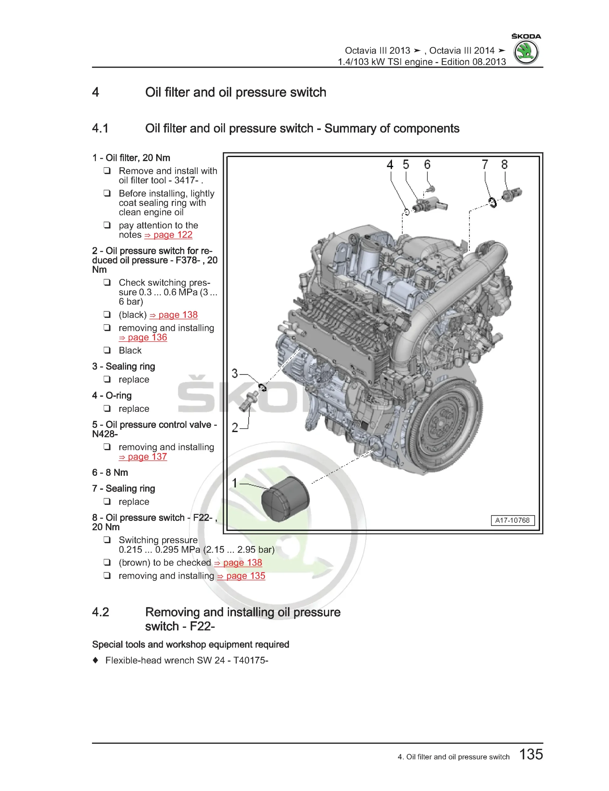
Oil filter and oil pressure switch – Summary of components
Removing and installing oil pressure switch F22
Removing and installing oil pressure switch for reduced oil pressure F378
Removing and installing valve for oil pressure control N428
Testing oil pressure
Cooling System
Cooling system
Coolant hose schematic diagram
Draining and filling coolant
Checking cooling system for leaks
Coolant pump and map-controlled engine cooling
The coolant pump and coolant regulator – List of assembly parts
Electric coolant pump – Summary of components
Coolant temperature sender – Summary of components
Removing and installing coolant pump
Removing and installing toothed belt pulley for coolant pump
Removing and installing thermostat
Removing and installing coolant recirculation pump V51
Removing and installing coolant temperature sender G62
Remove and install the coolant temperature sender at the cooler outlet G83
Coolant pipes
Coolant pipe – Summary of components
Removing and installing coolant pipes
Radiator and radiator fan
Radiator and radiator fan – Summary of components
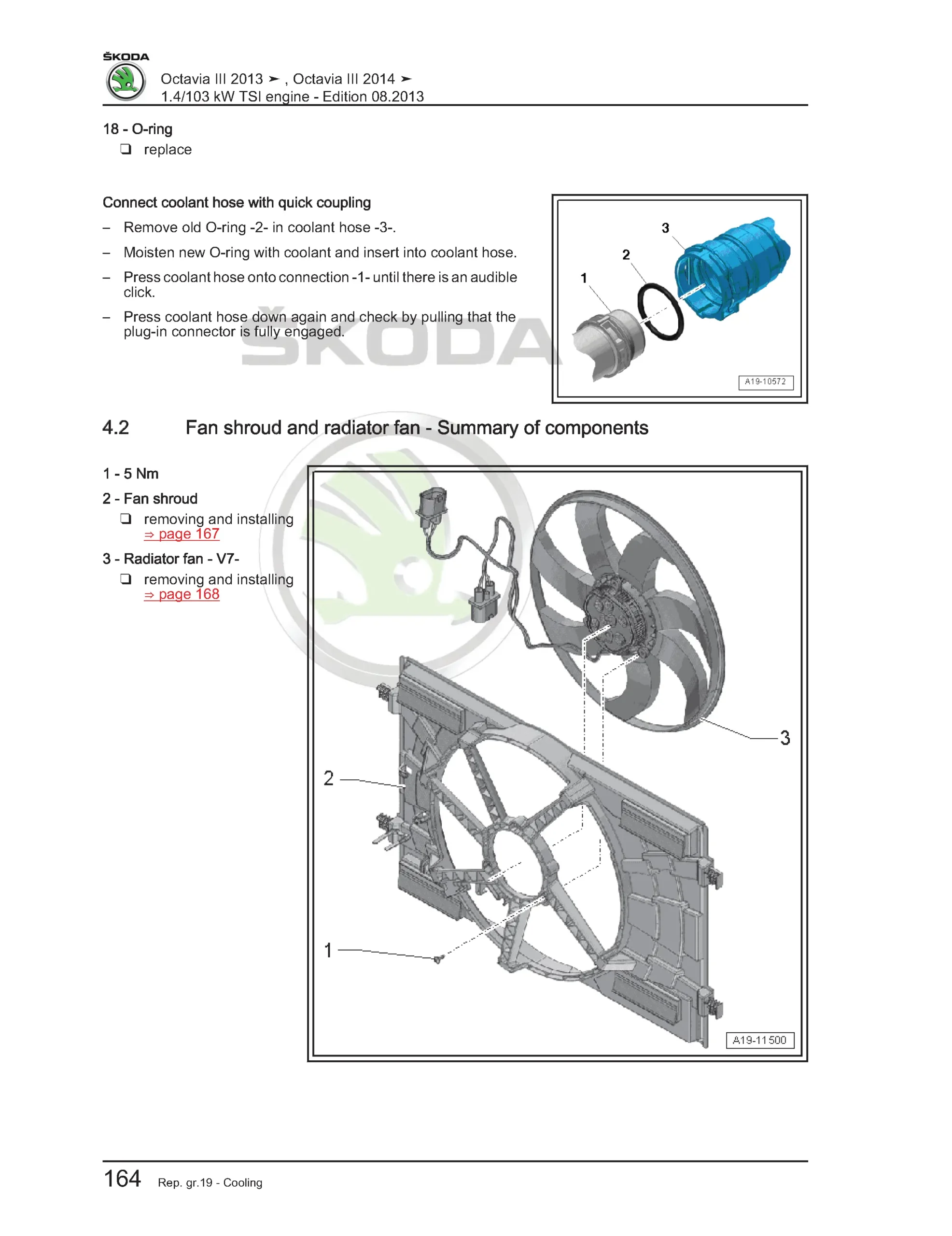
Fan shroud and radiator fan – Summary of components
Removing and installing radiator fan for coolant
Removing and installing fan shroud
Removing and installing radiator fan V7
Fuel Supply System
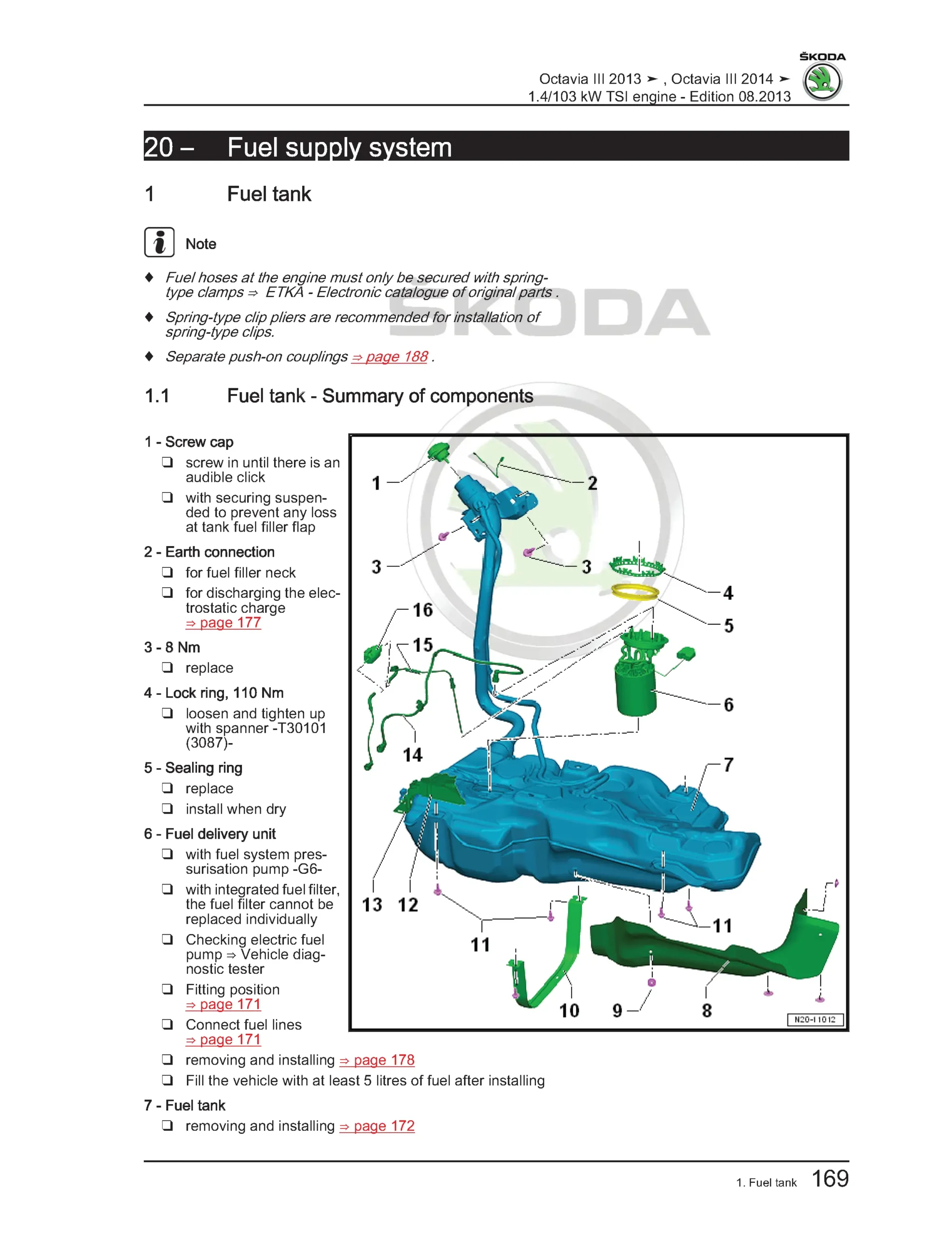
Fuel tank
Fuel tank – Summary of components
Extract fuel from the fuel tank
Removing and installing the fuel tank
Fuel delivery unit and sender for fuel gauge display
Summary of components
Removing and installing fuel delivery unit with sender for fuel gauge display
Removing and installing the sender for fuel gauge display G
Checking fuel pump
Removing and installing fuel pump control unit J538
Separating push-on couplings
Accelerator pedal
Accelerator pedal module – Summary of components
Removing and installing accelerator module
Activated charcoal filter system
Activated charcoal container system – Summary of components
Removing and installing activated charcoal filter
Turbocharging / Supercharging
Exhaust gas turbocharger
Exhaust turbocharger – Summary of components
Removing and installing exhaust gas turbocharger
Removing and installing charge pressure regulator V465
Charge-air system
Charge air system – Summary of components
Removing and installing charge pressure sender G31 with intake air temperature sender 2 G299
Removing and installing charge air cooler
Checking the charge-air system for leaktightness
Injection and Mixture Preparation
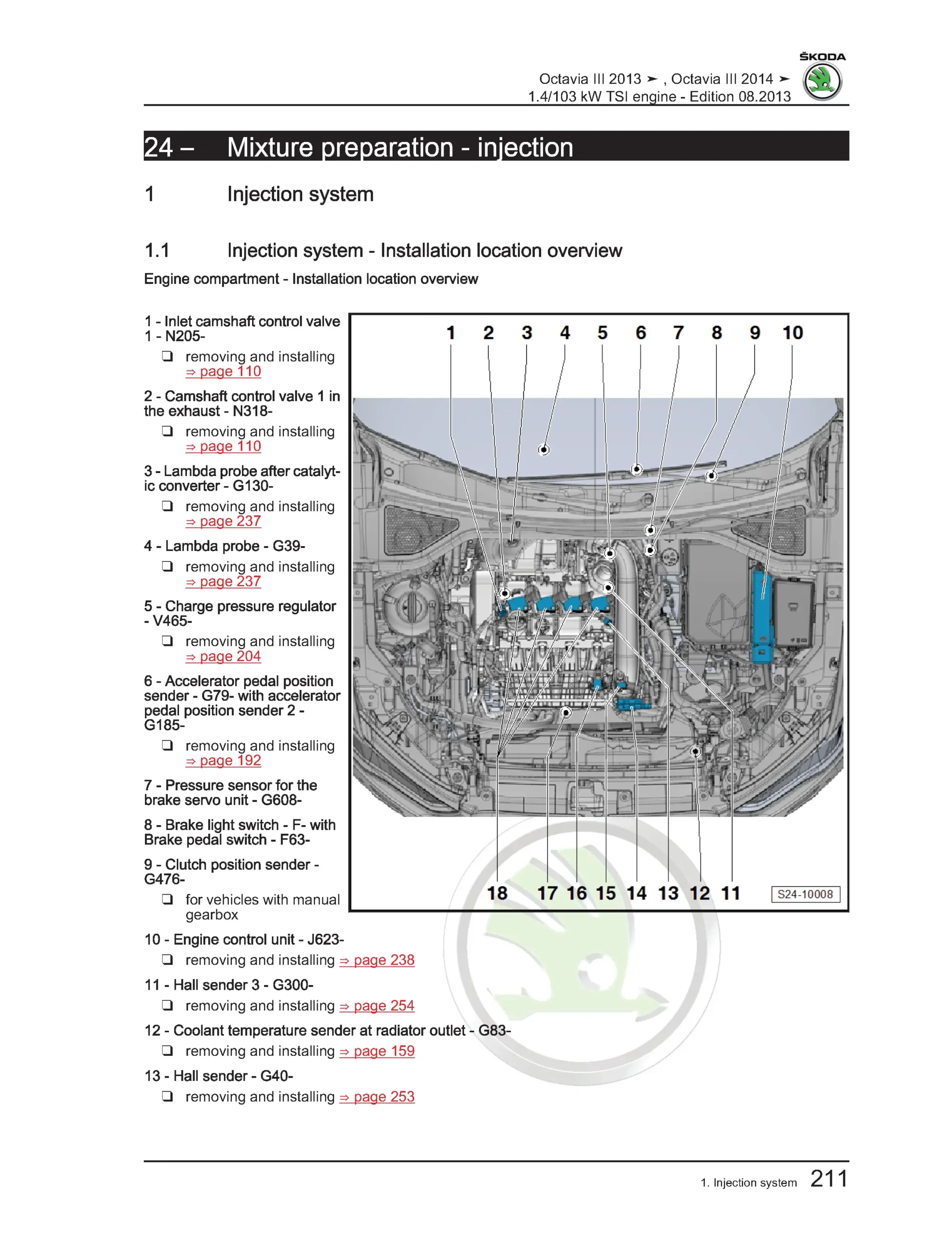
Injection system
Injection system – Installation location overview
Air filter
Air filter housing – Summary of components
Removing and installing air filter housing
Intake manifold
Intake manifold – Summary of components
Removing and installing intake manifold
Removing and installing the throttle valve control unit J338
Clean throttle valve control unit J338
Injectors
Fuel rail with injection valves – Summary of components
Removing and installing the fuel distributor
Removing and installing injectors
Clean injection valves
Senders and sensors
Removing and installing intake air temperature sender G42 with intake air temperature sender G71
Removing and installing fuel pressure sender G247
Check fuel pressure sender G247
High pressure pump
High pressure pump – Summary of components
Removing and installing the high pressure pump
Removing and installing high pressure pipe
Lambda probe
Lambda probe – Summary of components
Removing and installing lambda probe G39 / G130
Engine control unit
Removing and installing engine control unit J623 (without protective housing)
Removing and installing engine control unit J623 (with protective housing)
Exhaust System
Removing and installing parts of the exhaust system
Pre-exhaust pipe with catalytic converter – Summary of components
Removing and installing pre-exhaust pipe with catalytic converter
Middle or rear part of the exhaust system – Summary of components
Replacing middle or rear part of the exhaust system
Aligning exhaust system free of stress
Inspecting the exhaust system for leaktightness
Ignition System
Ignition system
Ignition system – Summary of components
Removing and installing ignition coils with output stage
Remove and install knock sensor 1 G61
Removing and installing Hall sender G40
Removing and installing hall sender 3 G300
Removing and installing engine speed sender G28


Reviews
Clear filtersThere are no reviews yet.