




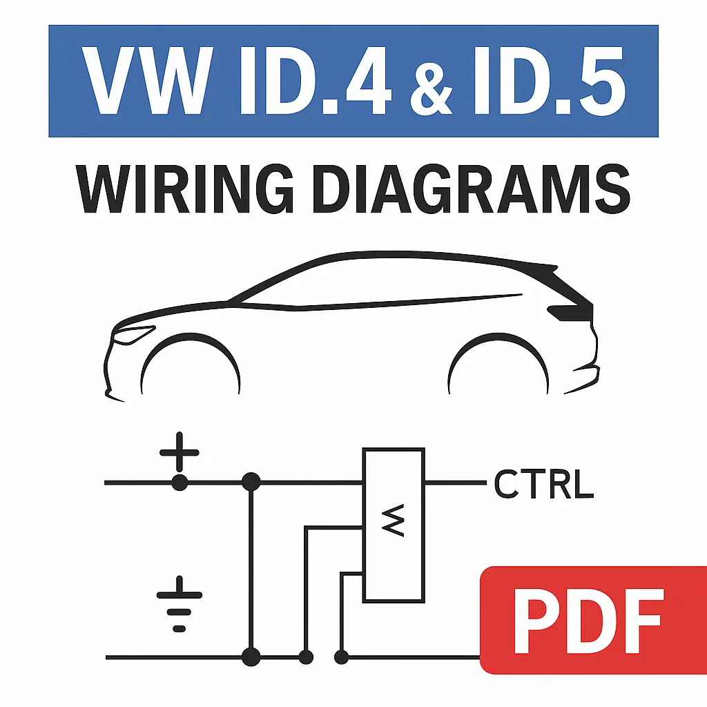

The Volkswagen ID.4 and ID.5 Wiring Diagrams Manual provides the complete set of factory current-flow schematics covering every high-voltage and low-voltage subsystem of the electric drive platform (EBJA / EBRA). Designed for diagnostic engineers and EV specialists, this manual details every signal path, connector pinout, CAN-bus layout, and ground point used in both rear-wheel and all-wheel drive configurations.
Manual Coverage
Electric Drive System (Rear Axle – EBJA)
-
Motor control unit (J623) and inverter architecture
-
Fuse holder layouts (B, C, interior)
-
CAN-bus connections between engine/motor control, power electronics, and steering column units
-
High-voltage lines (HV+ / HV–) with connectors T1–T2 series
-
Cooling circuit control: V468, V711 actuators, and radiator roller blind
Power and Control Electronics
-
Communication with data bus diagnostic interface (J533)
-
Integration of the ABS (J104) and thermal management system
-
Radiator fan (VX57), coolant pump (V468), and drive controller signal mapping
-
Detailed pin reference for connectors (T14, T17, T32, T40)
High-Voltage Battery System (J9D)
-
Complete schematics for high-voltage battery AX2
-
Fuse holder A/B/C with pilot signal routing
-
PTC heater circuits, cooling temperature senders G898–G899
-
Airbag (J234) and heater control interface (Z132)
-
Voltage converter (A19) and powertrain CAN-bus interconnections
Charging System & Power Conversion
-
DC/AC converters (A37, J1050, J842)
-
On-board charger (AX4) and HV charging socket (UX4)
-
High-voltage network junctions (TV43, TV77–TV92)
-
Battery contactors (J1052–J1058) and switching units SX7/SX8
Battery Regulation & Module Communication
-
Control logic for J840 battery regulation unit and J1208 module controller
-
Serial signal chain through battery modules J991–J994
-
Full 22-pin and 32-pin connector references (T22ab–T22ac)
-
CAN-bus routing between J840, J1208, and module harnesses
-
Diagnostic access points for cell voltage monitoring
CAN-Bus & Signal Reference
-
Comprehensive mapping of Powertrain, High-Voltage, and Thermal Management CAN networks
-
Connection points (B383–B396, E131–E134, A242–A245)
-
Wire color identification table (ws, sw, rt, br, gn, bl, gr, ge, vi, or, rs)
Earth & Fuse Reference Index
-
Detailed ground point locations (e.g., 238, 638, 674, 782)
-
Fuse assignments and amperage (SC22, SB23, SA1, etc.)
-
Applicable references for U.S. and EU market models
Delivery

Reviews
Clear filtersThere are no reviews yet.