Comprehensive workshop manual for Audi A3 (8V) covering technical data, engine maintenance, and safety precautions. Perfect for mechanics and car enthusiasts.
Format: PDF
Pages: 706
Delivery: The download link will be promptly delivered to your email upon completing the checkout process.
Covered Audi Vehicles:
- Audi A3 2013 ➤
- Audi A3 Sportback China 2014 ➤
Covered Engine IDs: CMBA, CPTA, CJZA, CXSA, CXSB, CSSA, CYVB, CZCA, CZEA, CUKB, CXUA, DBWA, CWLA, CZCC, DJSA, DGEA
List of Workshop Manual Repair Groups:
- Technical data
- Removing and installing engine
- Crankshaft group
- Cylinder head, valve gear
- Lubrication
- Cooling
- Turbocharging/supercharging
- Mixture preparation – injection
- Exhaust system
- Ignition system
- Electric drive systems
Contents:
- Technical data
- Identification
- Engine number/engine data
- Safety precautions
- Safety precautions when working on vehicles with high-voltage system
- Safety precautions when working in the vicinity of high-voltage components
- Safety precautions when working on the fuel supply system
- Safety precautions when working on vehicles with start/stop system
- Safety precautions when using testers and measuring instruments during a road test
- Safety precautions when working on the ignition system
- Safety precautions when working on the cooling system
- Safety precautions when working on the exhaust system
- Assessing high-voltage system risk level
- Necessary qualifications
- Work that requires high-voltage system to be de-energised
- Repair instructions
- Work on high-voltage components or potential equalisation lines
- Rules for cleanliness
- Foreign particles in engine
- Contact corrosion
- Routing and attachment of pipes, hoses and wiring
- Nuts, bolts
- Identification plates
- Use of impact wrenches
- Installing radiators and condensers
- Checking vacuum system
- General notes
- Painting work on vehicles with high-voltage system
- Removing and installing engine
- Removing and installing engine
- Removing engine
- Separating engine and gearbox
- Securing engine to engine and gearbox support
- Installing engine
- Assembly mountings
- Exploded view – assembly mountings
- Supporting engine in installation position
- Removing and installing engine mountings
- Removing and installing gearbox mounting
- Removing and installing pendulum support
- Checking adjustment of assembly mountings (engine/gearbox mountings)
- Adjusting assembly mountings
- Engine cover panel
- Removing and installing engine cover panel
- Crankshaft group
- Cylinder block (pulley end)
- Exploded view – poly V-belt drive
- Exploded view – sealing flange (pulley end)
- Plug for “TDC” drilling in cylinder block – tightening torque
- Removing and installing poly V-belt
- Removing and installing tensioner for poly V-belt
- Removing and installing engine support
- Removing and installing pulley
- Renewing crankshaft oil seal (pulley end)
- Removing and installing sealing flange (pulley end)
- Cylinder block (gearbox end)
- Exploded view – cylinder block (gearbox end)
- Removing and installing flywheel
- Removing and installing sealing flange (gearbox end)
- Crankshaft
- Crankshaft dimensions
- Measuring axial clearance of crankshaft
- Renewing needle bearing in crankshaft
- Pistons and conrods
- Exploded view – pistons and conrods
- Removing and installing pistons
- Removing and installing oil spray jets
- Checking pistons and cylinder bores
- Checking radial clearance of conrod bearings
- Cylinder head, valve gear
- Toothed belt drive
- Exploded view – toothed belt cover
- Exploded view – toothed belt
- Detaching toothed belt from camshaft
- Removing and installing toothed belt
- Cylinder head
- Exploded view – cylinder head
- Removing and installing cylinder head
- Removing and installing camshaft housing
- Checking compression
- Valve gear
- Exploded view – valve gear
- Removing and installing cam actuators
- Removing and installing camshaft control valve 1 N205
- Measuring axial clearance of camshaft
- Removing and installing camshaft oil seal
- Removing and installing valve stem oil seals
- Inlet and exhaust valves
- Checking valve guides
- Checking valves
- Valve dimensions
- Lubrication
- Sump/oil pump
- Exploded view – sump/oil pump
- Removing and installing oil level and oil temperature sender G266
- Removing and installing sump
- Removing and installing oil pump
- Engine oil
- Engine oil cooler
- Exploded view – engine oil cooler
- Removing and installing engine oil cooler
- Crankcase breather
- Exploded view – crankcase breather system
- Removing and installing oil separator
- Oil filter/oil pressure switches
- Exploded view – oil filter/oil pressure switches
- Removing and installing oil pressure switch F22
- Removing and installing oil pressure switch F1 / F378
- Removing and installing valve for oil pressure control N428
- Checking oil pressure
- Cooling
- Cooling system/coolant
- Connection diagram – coolant hoses
- Checking cooling system for leaks
- Draining and filling cooling system
- Connecting coolant hose with plug-in connector
- Coolant expansion tank
- Exploded view – coolant expansion tank
- Removing and installing coolant expansion tank
- Coolant pump/thermostat assembly
- Exploded view – coolant pump/thermostat
- Exploded view – electric coolant pump
- Exploded view – coolant temperature senders
- Exploded view – coolant valves
- Removing and installing coolant pump
- Removing and installing toothed belt sprocket for coolant pump
- Removing and installing thermostat
- Removing and installing electric coolant pump
- Removing and installing coolant temperature sender G62
- Removing and installing radiator outlet coolant temperature sender G83
- Removing and installing coolant temperature sender for heater G241
- Removing and installing engine temperature sender 2 G652
- Removing and installing coolant valves
- Coolant pipes
- Exploded view – coolant pipes
- Removing and installing coolant pipes
- Radiators/radiator fan
- Exploded view – radiators/radiator fan
- Exploded view – radiator cowl and radiator fan
- Removing and installing radiator
- Removing and installing radiator cowl
- Removing and installing radiator fan
- Turbocharging/supercharging
- Turbocharger
- Exploded view – turbocharger
- Removing and installing turbocharger
- Renewing vacuum unit for turbocharger
- Removing and installing charge pressure positioner V465
- Removing and installing connection for turbocharger
- Charge air system
- Exploded view – charge air system
- Exploded view – hose connections for charge air system
- Removing and installing charge pressure sender G31 / intake air temperature sender 2 G299
- Removing and installing charge air cooler
- Mixture preparation – injection
- Injection system
- Overview of fitting locations – injection system
- Air cleaner
- Exploded view – air cleaner housing
- Removing and installing air cleaner housing
- Intake manifold
- Exploded view – intake manifold
- Removing and installing intake manifold
- Removing and installing throttle valve module GX3
- Cleaning throttle valve module GX3
- Removing and installing activated charcoal filter solenoid valve 1 N80
- Injectors
- Exploded view – fuel rail with injectors
- Removing and installing fuel rail
- Removing and installing injectors
- Cleaning injectors
- Senders and sensors
- Removing and installing intake air temperature sender G42 / intake manifold pressure sender G71
- Removing and installing fuel pressure sender G247
- Checking fuel pressure sender G247
- Removing and installing pressure differential sender for particulate filter G1037
- High-pressure pump
- Exploded view – high-pressure pump
- Removing and installing high-pressure pump
- Removing and installing high-pressure pipe
- Lambda probe
- Exploded view – Lambda probe
- Removing and installing Lambda probe
- Engine control unit
- Removing and installing engine/motor control unit J623
- Exhaust system
- Exhaust pipes/silencers
- Exploded view – silencers
- Removing and installing silencers
- Separating exhaust pipes/silencers
- Stress-free alignment of exhaust system
- Checking exhaust system for leaks
- Emission control system
- Exploded view – emission control system
- Exploded view – retainers and pipes for pressure differential sender for particulate filter G1037
- Removing and installing catalytic converter
- Removing and installing particulate filter
- Exhaust gas temperature control
- Exploded view – exhaust gas temperature control
- Removing and installing parts of exhaust gas temperature control
- Secondary air system
- Exploded view – secondary air system
- Removing and installing secondary air pump motor V101
- Removing and installing sender 1 for secondary air pressure G609
- Ignition system
- Ignition system
- Exploded view – ignition system
- Test data – spark plugs
- Removing and installing ignition coils
- Removing and installing knock sensor 1 G61
- Removing and installing Hall senders
- Removing and installing engine speed sender G28
- Electric drive systems
- High-voltage components
- Overview of fitting locations – high-voltage components
- Checking high-voltage components and high-voltage wiring
- Warning labels
- Checking warning labels
- High-voltage battery unit
- Exploded view – high-voltage battery
- Inspection and classification of hybrid battery unit AX1
- Removing and installing hybrid battery unit AX1
- Performing leak test for high-voltage battery
- Checking for high-voltage battery leaks
- Raising high-voltage battery
- Storing and transporting high-voltage batteries
- Removing and installing battery regulation control unit J840
- Repairing high-voltage battery
- Overview of fitting locations – high-voltage battery
- Overview of fitting locations – battery modules
- Overview of fitting locations – high-voltage connecting brackets
- Exploded view – battery housing
- Exploded view – switching unit for high-voltage battery SX6
- Exploded view – battery module assembly
- Exploded view – traction network connector mounting
- Exploded view – high-voltage battery cooling system
- Performing leak test on cooling system for hybrid battery unit AX1
- Determining mean cell voltage
- Charging and discharging battery modules
- Opening hybrid battery unit AX1
- Removing and installing switching unit for high-voltage battery SX6
- Removing and installing battery module assembly
- Removing and installing traction network connector mounting
- Removing and installing coolant temperature sender 1 for high-voltage battery G898 and coolant temperature sender 2 for high-voltage battery G899
- Bonding hybrid battery unit AX1
- Removing and installing battery module 1 J991 / battery module 2 J992
- Removing and installing battery module 3 J993 / battery module 4 J994
- Removing and installing battery module 5 J995 / battery module 6 J996
- Removing and installing battery module 7 J997 / battery module 8 J998
- Power and control electronics for electric drive
- Exploded view – power and control electronics for electric drive
- Exploded view – bracket for power and control electronics for electric drive
- Removing and installing power and control electronics for electric drive
- Removing and installing bracket for power and control electronics for electric drive JX1
- Removing and installing high-voltage system fuse 3 S353
- Charging unit for high-voltage battery
- Exploded view – charging unit for high-voltage battery
- Removing and installing charging unit 1 for high-voltage battery AX4
- Removing and installing bracket for charging unit 1 for high-voltage battery AX4
- Electric drive motor
- Removing and installing three-phase current drive VX54
- Removing and installing drive motor temperature sender G712
- Removing and installing drive motor rotor position sender 1 G713
- High-voltage wiring
- Overview of fitting locations – high-voltage wires
- Removing and installing high-voltage wiring harness for high-voltage battery
- Removing and installing high-voltage wiring harness for drive motor
- Removing and installing high-voltage wire for power and control electronics for electric drive
- Removing and installing high-voltage wire for high-voltage heater (PTC)
- Removing and installing high-voltage wire for electrical air conditioner compressor
- Charging socket
- Exploded view – charging socket
- e-tron charging system
- USB adapter for e-tron charging system
- Removing and installing high-voltage battery charging socket 1 UX4
- De-energising high-voltage system
- Re-energising high-voltage system
- Potential equalisation lines
- General notes – potential equalisation lines
- Overview of fitting locations – potential equalisation lines
- Removing and installing potential equalisation lines
- Engine sound generation
- Overview of fitting locations – engine sound generation
- Removing and installing engine sound generator control unit J943
- Removing and installing actuator 1 for engine sound generator R257





 Abrites AVDI J2534
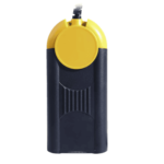 Actia Multi-Diag
 Autoland iSCAN
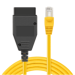 BMW ENET
 Bosch Mastertech II J2534
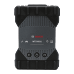 Bosch MTS 6531
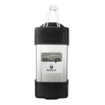 CAN CLIP RLT2002
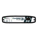 CarDAQ-Plus 3
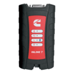 Cummins INLINE Datalink
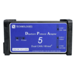 Dearborn Protocol Adapter (DPA) 5
 Delphi/Autocom DS150E
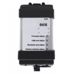 Volvo VIDA DiCE
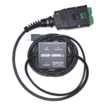 Derelek USB DIAG 3
 Electronic Data Link (EDL) 2
 Electronic Data Link (EDL) 3
 GM MDI 1
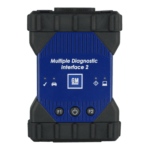 GM MDI 2
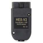 HEX-V2 VCDS VAG-COM
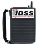 Isuzu IDSS IDS MX1
 Isuzu IDSS IDS MX2
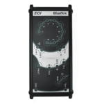 Iveco Eltrac E.A.SY. ECI
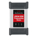 MaxiFlash Elite J2534
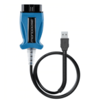 Mongoose J2534
 Nexiq USB-Link 1
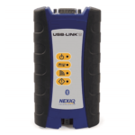 Nexiq USB-Link 2
 Nexiq USB-Link 3
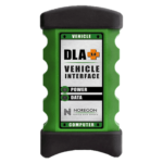 Noregon DLA+ 2.0
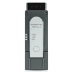 Porsche PIWIS TESTER 3 (PT3G)
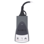 PSA LEXIA 3
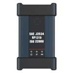 SAE J2434
 Scania VCI 3
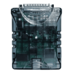 Scanmatik 2 PRO
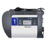 SD Connect Multiplexer
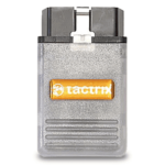 Tactrix OpenPort 2.0
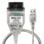 Toyota TIS Mini VCI
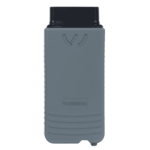 VAG ODIS VAS5054 Clone
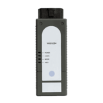 VAG ODIS VAS6154 Clone
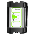 Volvo VOCOM 1
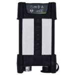 Volvo VOCOM 2






Reviews
Clear filtersThere are no reviews yet.