


Technical Highlights
- Full ECM pinout (Connector A & B layout)
- VP44 fuel system integration:
- Fuel pump control module
- Fuel shutoff
- Power and datalink circuits
- Sensor circuits:
- Engine position & speed sensors
- Oil pressure sensor
- Intake manifold pressure
- Intake air & coolant temperature
- Throttle & control systems:
- Accelerator position sensor (+5V, signal, return)
- Idle validation signals
- Cruise control & PTO functions
- Communication:
- J1939 data link
- J1587 service data link
- Diagnostic systems:
- Red, yellow, engine protection lamps
- Wait-to-start & water-in-fuel indicators
- Actuators:
- Lift pump
- Fan clutch
- Intake air heater
- Power distribution:
- Battery supply, ignition, and fuse circuits
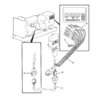
👉 The diagram on page 1 clearly shows ECM connections to VP44 system, sensors, and actuators, along with full connector mapping and signal routing.
Table of Content
- ECM Connector A & B Layout
- VP44 Fuel System Wiring
- Sensor Network (Pressure / Temperature / Speed)
- Accelerator & Idle Validation System
- Cruise Control & PTO Circuits
- Diagnostic Lamps & Indicators
- Data Link Communication (J1939 / J1587)
- Actuator Control (Lift Pump, Fan Clutch, Heater)
- Power Supply & Ground Distribution
File Information
- Manufacturer: Cummins
- System: ISB Engine Management
- Fuel System: VP44
- Document Type: Wiring Diagram
- Bulletin: 3666195-02
- Format: PDF
- Pages: 1
- Content: Electrical Schematics, Pinout, Fuel & Sensor Systems


Reviews
Clear filtersThere are no reviews yet.