


This professional factory repair manual provides full technical coverage for the IVECO New Daily commercial vehicle platform, including Euro 5 and Euro VI engine configurations.
Designed for workshop technicians, diagnostic specialists, and fleet maintenance professionals, this manual includes complete mechanical procedures, electrical system documentation, diagnostic workflows, and scheduled maintenance operations.
Covers All Major Vehicle Systems
The documentation includes detailed repair procedures and technical specifications for:
Engine mechanical systems and fuel injection
Manual and automatic gearboxes
Electric retarders and drivetrain components
Suspension and axle systems
Hydro-pneumatic braking systems
Steering and wheel assemblies
Bodywork, chassis, HVAC, and auxiliary heaters
Full electrical and electronic architecture
All sections include tightening torques, servicing procedures, removal instructions, overhaul processes, and troubleshooting data.
Electrical & Electronic Diagnostics Included
The manual provides extensive electrical documentation including:
Complete vehicle grounding architecture
CAN network systems
ECU control modules
Sensor and actuator documentation
Lighting systems and body electronics
Immobilizer and central locking systems
Start & Stop system
SCR / AdBlue components
This makes it suitable for advanced diagnostics and ECU troubleshooting.
Factory Maintenance & Service Procedures
Includes official maintenance schedules and service operations such as:
Oil and filter replacement procedures
Brake inspections and servicing
Cooling system maintenance
Timing system replacements
Differential and gearbox servicing
Scheduled inspection programs
These procedures match manufacturer workshop specifications.
Technical Highlights
Official manufacturer workshop documentation
Covers Euro 5 and Euro VI engines
Includes full mechanical overhaul procedures
Complete electrical system diagnostics
Step-by-step removal and refitting operations
Suitable for professional workshop use
Delivery
The download link will be promptly delivered to your email upon completing the checkout process.- Repair Manual
- General information
- Engine
- Clutch
- Gearbox
- Electric retarders
- Propeller shafts
- Rear axles
- Axles
- Suspensions
- Wheels and tyres
- Steering
- Hydro-pneumatic system – Brakes
- Bodywork and chassis
- Scheduled maintenance
- Electric/electronic system
- Introduction
- Symbols – warnings
- Symbols – service operations
- Product code
- General warnings
- General warnings regarding the electrical system
- Grounding and screening
- Optional electrical and mechanical parts installations
- Conversions between the main units of measurement of the international system and the most commonly used derived sizes
- Power
- Torque
- Revolutions per time unit
- Pressure
- Temperature
- Update data
- General information
- Acronyms used in the section
- Identification data
- Vehicle identification number (V.I.N.) punched on the chassis
- Engine block marking
- Vehicle identification plate
- Product identification plate
- Technical and commercial coding
- Technical coding
- Commercial coding
- Composition of models
- Alphanumerical coding of vehicle identification
- PIC coding – EURO 5 / Euro VI engines
- Refuelling
- Engine
- FIA Euro 5 engines
- Engines FIC Euro 5+ / Euro VI
- Diagnostics
- FIA Euro 5 engines – Contents
- Acronyms used in the section
- Engine views
- FIAFL411 engine identification
- Self-adhesive label description on engine
- Engine block marking
- Characteristic curves
- Power supply system description
- Electronic injection control
- System operation
- Operation
- Hydraulic system description
- Fuel pipe description
- Description of electric fuel pump
- Description of fuel filter
- Description of high pressure pump
- Description of flow rate regulator
- Rail description
- Electro-injector description
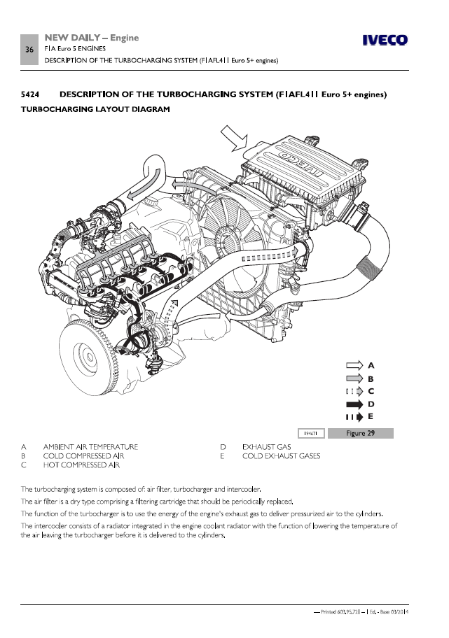
- Description of the turbocharging system (Euro 5+ engines)
- Turbocharging layout diagram
- Turbocharging operating diagram
- Turbocharger description (WG MHI type)
- Turbocharger description (variable geometry type)
- Proportional solenoid valve description
- Actuator description
- Timing description
- Lubrication description
- Oil and vacuum pump assembly description
- Oil pressure regulator valve description
- Oil filter description
- Heat exchanger description
- Oil vapour recirculation system description
- Engine cooling system description
- Electro-magnetic pulley description
- Water pump description
- Thermostat description
- EGR exhaust gas recirculation system description
- E.G.R. valve description
- Air flow rate meter description
- Throttle valve description
- Heat exchanger description
- System for reducing polluting substances at exhaust (Euro 5+ vehicles)
- Catalytic converter / DPF description
- Particulate filter regeneration system
- Change engine oil
- Emission values
- Start & Stop system
- Location of components
- Electric/electronic component description
- Electronic control unit description
- Glow plugs control unit description
- Glow plugs description
- Engine speed sensor description
- Camshaft timing sensor description
- Air temperature and pressure sensor description
- Fuel temperature sensor description
- Fuel pressure sensor description
- Atmospheric pressure sensor description
- Engine coolant temperature sensor description
- Accelerator pedal position sensor description
- Clutch pedal position sensor description
- Brake pedal position sensor description
- Vehicle speed sensor description
- Differential pressure sensor description
- Exhaust gas temperature sensor description
- Lambda probe description
- Actuator description
- General characteristics
- Data – installation clearances
- Tightening torques
- Tools
- Test equipment
- Main servicing operations to be performed on engine fitted on vehicle
- Removal-refitting of engine
- Replacement of the engine control unit (EDC)
- Air filter replacement
- Replacement of air filter cartridge
- Change engine coolant
- Replacement of belts on the vehicle
- Replacement of injectors on vehicle
- Removal-refitting the cylinder head on the vehicle
- High pressure pump replacement on the vehicle
- Common rail fuel pressure sensor removal-refitting
- Replacing the water pump on the vehicle
- Removing-refitting the throttle valve
- Air flow meter replacement
- Remove-refit turbocharging air pressure sensor
- Replace the preheating glow plugs
- Replacing the E.G.R. heat exchanger on the vehicle
- Replacement of the E.G.R. valve on the vehicle
- Oil sump removal-refitting
- Replacing engine oil sump
- Replacing D.P.F. catalytic converter
- Replacement of differential sensor (delta-p)
- Lambda sensors removal-refitting
- Replacement of fuel aspiration unit
- Overhauling the engine
- Disassembling the engine on the workbench
- Engine block measurements and checks
- Crankshaft measurements and checks
- Repairs on turbocharger
- Piston-connecting rod assembly overhaul
- Cylinder head overhaul
- Overhead overhaul
- Assembly of engine on workbench
- Clutch
- Acronyms used in the section
- General information
- Section of clutch assembly
- Hydraulic clutch drive assembly description
- Clutch hydraulic assembly characteristics (10" 1/2)
- Clutch hydraulic assembly characteristics (11")
- Clutch hydraulic assembly characteristics (12")
- Master cylinder
- Slave cylinder
- Automatic wear recovery device
- Description
- Operation
- Characteristics and data
- Valeo variants
- AP variants
- Sachs variants
- Tightening torques
- Tools
- Clutch removal-refitting
- Hydraulic clutch drive assembly removal/installation
- Pedal assembly repairs
- Removal and installation of clutch with automatic wear recovery device
- Diagnostics
- Noise when clutch pedal is pressed
- Noise when the pedal is released
- Clutch jerks
- The clutch does not release
- The clutch slips
- Abnormal wear of driven disc linings
- Gearbox
- Main repair operations on vehicle mechanical gearboxes
- Main repair operations on vehicle automatic gearboxes
- Gear 2835.6 D.O.D.
- Gear 2840.6 O.D.
- Gear 2850.6 D.O.D.
- 6AS 400 O.D. automatic gearbox
- Power take-offs
- Diagnostics
- Main repair operations on vehicle mechanical gearboxes
- Acronyms used in the section
- Main assembly standards
- Gearbox control tightening torques
- Removal-refitting of mechanical gearboxes
- Gear drive flexible cable replacement
- Check and adjustment of gear control
- Removal-refitting of control lever mount
- Electric retarders
- Electric retarders
- Diagnostics
- Electric retarders – Contents
- Acronyms used in the section
- Vehicle-retarder pairing table
- Overview of retarder Telma LVRS 350
- Overview of retarder Telma LVRS 600
- Assembly diagram and tightening torques (LVRS 350)
- Assembly diagram and tightening torques (LVRS 600)
- Propeller shafts
- Acronyms used in the section
- Camshaft description
- Characteristics and data
- Fixed propeller shaft
- Sliding propeller shaft
- Single section articulated transmission shaft
- Propeller shaft articulated in 3 parts
- Flexible coupling
- Tightening torques
- Camshaft removal and refitting
- Propeller shaft overhaul
- Diagnostics
- Noisy and vibrating transmission
- Rear axles
- NDA-RS rear axle
- NDA-RG rear axle
- Rear axle 450511
- Rear axle 450517/2
- Diagnostics
- NOA-RS rear axle – Contents
- Acronyms used in the section
- Description
- Characteristics and data
- Tightening torques
- Central part
- Wheel side
- Tools
- Removal-refitting of rear axle
- Rear axle assembly overhaul
- Axles
- Mecbal axle 30S-33S-35S
- Mecbal axle 35C-40C
- Hector 35C-50C axle
- Hector 60C-70C axle
- Wheel trim
- Diagnostics
- Mecbal axle 30S-33S-35S – Contents
- Acronyms used in the section
- Description
- Characteristics and data
- Tightening torques
- Tools
- Test equipment
- Removal-refitting of Mecbal front axle
- Overhaul of Mecbal axle 30S-33S-35S
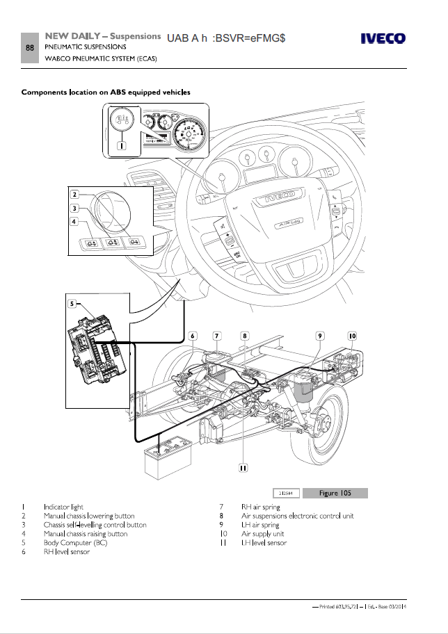
- Suspensions
- Mechanical suspensions
- Pneumatic suspensions
- Mechanical suspensions – Contents
- Acronyms used in the section
- Front mechanical suspensions
- General information
- Characteristics and data
- Tightening torques
- Tools
- Repair operations
- Rear mechanical suspension
- General information
- Characteristics and data
- Tightening torques
- Tools
- Repair operations
- Diagnostics
- Noisy suspension
- The vehicle tends to drift to one side
- Excessive suspension flexibility
- Excessive suspension stiffness
- Wheels and tyres
- Acronyms used in the section
- Description
- Tightening torques
- Static wheel balancing
- Correction of residual static imbalance
- Tyre pressure
- Tyre behaviour in relation to pressure
- Diagnostics
- Excessive wear
- Irregular wear
- The vehicle pulls to one side
- Steering
- Acronyms used in the section
- General information
- Power steering
- Description
- ZF type power steering
- Operation
- Steering system assembly diagram
- Power steering characteristics and data
- Tightening torques
- Tools
- Safety requirements for vehicles equipped with airbags
- Checks and repairs on the vehicle
- Diagnostics
- Steering stiff when turning right and left
- Steering stiff only when turning left or right
- Steering stiff when the wheel is turned quickly
- Hard knocks on the steering wheel when steering
- Torsional vibration of the steering wheel
- Excessive steering wheel clearance
- Oil leak
- Insufficient pressure in the circuit
- The vehicle pulls to one side (ZF steering box only)
- Power steering fluid warning light always on
- Hydro-pneumatic system – Brakes
- Acronyms used in the section
- Brake system general information
- Types of braking
- Types of brake calipers
- Stability control and anti-skid devices
- Symbols used in the air/hydraulic system diagrams
- Graphic symbols for air/hydraulic system diagrams (semi-couplings and coupling heads)
- Diagram of ancillary equipment
- Location on the vehicle of main brake system components
- Braking system main component description
- Vacuum pump description
- Vacuum servobrake description
- Vacuum tank description
- ABS/ESP electronic control unit description
- ABS/ESP electro-hydraulic modulator description
- Revs sensor
- Pulser rings
- Steering angle sensor
- Characteristics and data – hydraulic system
- Characteristics and data – brakes
- Tightening torques
- Tools
- Brake system repairs on vehicle
- Bleeding air from the hydraulic circuit (without ABS – front)
- Bleeding air from the hydraulic circuit (without ABS – rear)
- Bleeding air by means of bleeding device (without ABS)
- Bleeding air (with ABS/ESP)
- Mechanically controlled braking corrector description
- Adjusting the braking corrector on the vehicle
- Front brakes repairs
- Rear brakes repairs
- Brake calliper overhaul
- Overhaul of the brake discs
- Parking brake overhaul
- ESP component replacement
- Bodywork and chassis
- Body – chassis
- Acronyms used in the section
- Outswinging door description
- Cab air-conditioning
- Ventilation
- Climate control
- Climate control system operating diagram
- Air conditioning compressor description
- Condenser description
- Drier filter description
- Expansion valve description
- Evaporator description
- Pressure switch description
- Outside air temperature sensor positioning
- Quantity of coolant in the air-conditioning system
- Webasto additional heater description
- Auxiliary heating system diagram
- Location on the vehicle
- Main components
- Coolant pump description
- Fuel pump description
- Supplementary heater operation
- Parking heater operation
- Characteristic data
- Tightening torques
- Tools
- Repair operations on vehicle
- Cab repair interventions
- Air conditioner repairs
- Repair operations on doors
- Outswinging door repairs
- Chassis repairs
- Chassis geometry check
- General precautions when working on the chassis
- Preparing the chassis for maintenance/inspection/repair work
- Spot welding
- Instructions for welding
- Operations to be carried out by the body builder on longitudinal members
- Drills on the chassis
- Chassis geometry checks
- Measuring lateral curvature
- Measuring vertical curvature
- Measuring chassis displacement
- Measuring position of the axles
- Measuring torsion of the chassis
- Reconditioning the chassis
- Welds on the chassis
- Diagnostics
- Main mechanical malfunctions – air conditioning system
- System noisy
- Compressor noise
- Strange noise with clutch connected
- Strange noise with friction disconnected or vibrations
- Auxiliary heater pump troubleshooting
- Main operating faults – supplementary heater
- Smell of fuel / fuel leakages
- Fails to reach full load
- White smoke at the exhaust
- Heater fails to turn off
- Coolant leakage
- Ignition switch diagnostics
- E.A.SY. connection
- Fault codes
- DTC codes – Denso air conditioning control unit
- DTC codes – Webasto additional heater control unit
- Scheduled maintenance
- Acronyms used in the section
- Maintenance services schedule
- Vehicles with engine Euro 5 FIA
- Standard services (M)
- Extra plan services (EP)
- Timed services (T)
- Vehicles with FIC Euro 5 / Euro VI engine
- Standard services (M)
- Extra plan services (EP)
- Timed services (T)
- Location of check – maintenance
- Standard services (M)
- Change engine oil
- Change engine oil filter
- Replace fuel pre-filter cartridge (if any)
- Check hydraulic brake system fluid level
- Change mechanical and automatic gearbox oil
- Check auxiliary drive belts
- Water pump and alternator drive belt replacement (FIC)
- Alternator drive belt replacement (FIA)
- Replace air conditioner compressor drive belts
- Check steering box rack boots
- Check front brake disc wear
- Check rear brake disc wear
- Check front brake pad wear
- Check rear brake pad wear
- Check parking brake stroke
- Clean rear axle oil breather
- Check steering box mounting
- Check linkage, steering joints and column
- Check universal joints and propeller shaft mounting
- Reset DPF regeneration with diagnostics tool
- Check engine EDC system with EASY system
- Headlight levelling check
- Bonnet opening/closing and engine guard operations
- Handling operations
- Functional road test
- Extra plan services (EP)
- Change differential rear axle oil
- Replace cartridge and clean air filter box
- Fuel filter replacement
- Replace timing belts (FIA engines only)
- Replace timing drive belt automatic tensioner (FIA engines only)
- Replace alternator movable belt tensioner
- Replace preheating glow plugs
- Timed services (T)
- Check pollen filter condition
- Engine coolant density check
- Replace supplementary heater fuel filter
- Change and bleed hydraulic brake system fluid
- Check density of heat exchanger coolant (two stage turbine)
- Electric/electronic system
- General information – electric/electronic system
- Connectors
- Circuit boards
- Diagnostics
- General information – Contents
- Abbreviations and graphic symbols
- General warnings
- Conventions
- Warning
- Understand the vehicle
- Ground and electromagnetic compatibility
- Construction characteristics
- Coupling welds
- Vehicle configuration
- Vehicle configuration modification
- Acronyms used in document
- Acronyms used in the EASY diagnostic tool
- Negative network (grounding points)
- Battery negative
- Chassis ground points
- Bonnet ground points
- Dashboard ground points
- Cab ground points
- Positive circuit
- Battery
- Battery control unit


Reviews
Clear filtersThere are no reviews yet.