





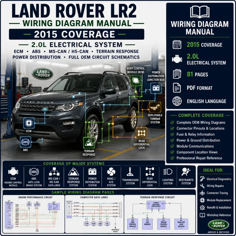

This Land Rover LR2 2015 wiring diagram manual provides complete electrical circuit schematics for the HSE Lux 2.0L model.
It is designed for professional diagnostics, electrical troubleshooting, module testing, wiring repair, connector tracing, retrofit planning and workshop repair reference.
The manual covers key vehicle systems including ECM engine control, ABS, Terrain Response, HS-CAN / MS-CAN communication networks, HVAC, cooling fan, body control modules, power distribution, ground distribution, exterior lighting, interior lighting, navigation, radio, restraints, transmission, rear differential lock, power seats, power windows, tailgate release and wiper/washer wiring.
Vehicle Coverage
- Land Rover LR2 2015 HSE Lux
- Engine: 2.0L
- Pages: 81
- Format: PDF
- Language: English
Technical Highlights
- Complete 2.0L engine performance wiring
- ECM / Engine Control Module circuits
- ABS and brake control wiring
- Terrain Response circuit
- HS-CAN, MS-CAN, LIN and MOST network diagrams
- Diagnostic socket and computer data line wiring
- Power distribution and fuse box diagrams
- Ground distribution circuits
- HVAC, A/C compressor and climate control circuits
- Cooling fan and engine coolant temperature sensor wiring
- Exterior lights, headlights, fog lamps and trailer-related lighting
- Interior lights, courtesy lamps and instrument illumination wiring
- Navigation, parking assistant and rear view camera circuits
- Radio high-line, low-line and fibre optic network circuits
- Power seats, heated seats and heated steering wheel wiring
- Power mirrors, power windows and power door lock circuits
- Starting, charging, shift interlock and steering column wiring
- Supplemental restraints, warning systems and wiper/washer circuits
- Transmission and rear differential lock wiring
Table of Content
- Air Conditioning
- Automatic A/C circuit
- Front blower motor control unit
- A/C compressor clutch and compressor solenoid wiring
- Air conditioning pressure sensor
- Evaporator temperature sensor
- In-vehicle temperature sensor
- Pollution sensor and HVAC door motor circuits
- Anti-Lock Brakes
- Anti-lock brake circuit
- Brake pedal switch
- Brake fluid level sensor
- ABS control module wiring
- Wheel speed sensor circuits
- Terrain Response circuit
- Electric park brake and instrument cluster data links
- Anti-Theft
- Active anti-theft circuit
- Passive anti-theft circuit
- Keyless vehicle module wiring
- Hood switch and volumetric sensor circuits
- Passive sounder and RF receiver wiring
- Immobilizer antenna unit wiring
- Door module and central locking security links
- Body Control Modules
- Body Control Module circuit
- Central junction box wiring
- BCM power, ground and signal circuits
- Exterior lighting, interior lighting and warning system links
- Door locks, tailgate, fuel door and wiper/washer links
- Starting/charging, engine control and restraint system links
- Computer Data Lines
- Diagnostic socket circuit
- HS-CAN communication circuits
- MS-CAN communication circuits
- LIN bus circuits
- MOST / fibre optic network circuit
- Data link connector wiring
- ECM, transmission, instrument cluster, climate and infotainment data links
- Cooling Fan
- Cooling fan circuit
- Cooling fan control unit wiring
- Engine coolant temperature sensor links
- ECM fan control and CAN data connections
- Cruise Control
- Cruise control circuit
- Steering wheel module links
- Brake pedal switch wiring
- Accelerator pedal position sensor
- ECM and transmission data connections
- Defoggers
- Heated mirrors circuit
- Heated windshield circuit
- Rear defogger circuit
- Engine Performance
- 2.0L Turbo engine performance circuit
- Engine Control Module / ECM wiring
- Ignition, fuel, sensor and actuator circuits
- Accelerator pedal position sensor
- Engine coolant temperature sensor
- A/C pressure sensor and cooling fan links
- Turbocharger and throttle-related engine control wiring
- Exterior Lights
- Backup lamps circuit
- Exterior lamps and trailer connector circuit
- Front and rear exterior lighting wiring
- Tail lamp, turn signal, marker lamp and license lamp wiring
- BCM-controlled lighting links
- Ground Distribution
- Ground distribution circuits
- Engine ground points
- Chassis ground points
- Body, HVAC, lighting, infotainment and module ground circuits
- Headlights
- Headlamps circuit
- Headlamp leveling circuit
- Fog lamp and headlamp control wiring
- Horn
- Horn circuit
- Horn relay and BCM horn control wiring
- Instrument Cluster
- Instrument cluster circuit
- Driver information display wiring
- Warning indicator and data line connections
- Interior Lights
- Courtesy lamps circuit
- Instrument illumination circuit
- Interior lighting and dimming control wiring
- Memory Systems
- Memory mirrors circuit
- Memory seat circuit
- Seat memory module wiring
- Navigation
- Navigation circuit
- Parking assistant circuit
- Rear view camera circuit
- Touch screen and infotainment wiring
- GPS, antenna and audio module connections
- Power Distribution
- Power distribution circuits
- Battery junction box wiring
- Central junction box wiring
- Rear junction box wiring
- Fuse, relay and ignition power circuits
- Module power supply diagrams
- Power Door Locks
- Power door locks circuit
- Door lock motor wiring
- Lock/unlock control circuits
- Keyless and anti-theft module links
- Power Mirrors
- Electrochromic mirror circuit
- Power mirrors circuit
- Heated mirror and mirror control wiring
- Power Seats
- Heated seats circuit
- Heated steering wheel circuit
- Power seats circuit
- Driver and passenger seat module wiring
- Power Top / Sunroof
- Power top / sunroof circuit
- Roof opening panel control wiring
- Power Windows
- Power windows circuit
- Window motor and switch wiring
- Door module window control links
- Radio
- Radio circuit, high line
- Radio circuit, low line
- Audio amplifier wiring
- Touch screen and integrated audio module wiring
- Fibre optic network circuit
- MOST diagnostic connector wiring
- Shift Interlock
- Park brake release circuit
- Shift interlock circuit
- Steering column circuit
- Starting / Charging
- Charging circuit
- Starting circuit
- Starter, generator and battery supply wiring
- Supplemental Restraints
- Supplemental restraints circuit
- Restraint control module wiring
- Airbag, impact sensor and seat belt-related circuits
- Transmission
- Automatic transmission circuit
- Rear differential lock circuit
- Transmission Control Module wiring
- Trunk, Tailgate, Fuel Door
- Tailgate and fuel door release circuit
- Rear body and release switch wiring
- Warning Systems
- Warning systems circuit
- Cluster warning and system indicator wiring
- Wiper / Washer
- Front wiper/washer circuit
- Jet heater circuit
- Power wash circuit
- Rear wiper/washer circuit

Reviews
Clear filtersThere are no reviews yet.