


This technical wiring manual contains the complete electrical schematics for the electronic parking brake (EPB) system used in MAN TG3 trucks.
The diagrams include the full control architecture for the EPB control unit, parking brake operating switch, CAN communication networks, fuse protection circuits, pressure monitoring sensors, and electrical supply routing.
All circuits include connector identifiers, CAN bus topology references, and grounding architecture required for professional diagnostics, repair, or retrofit work.
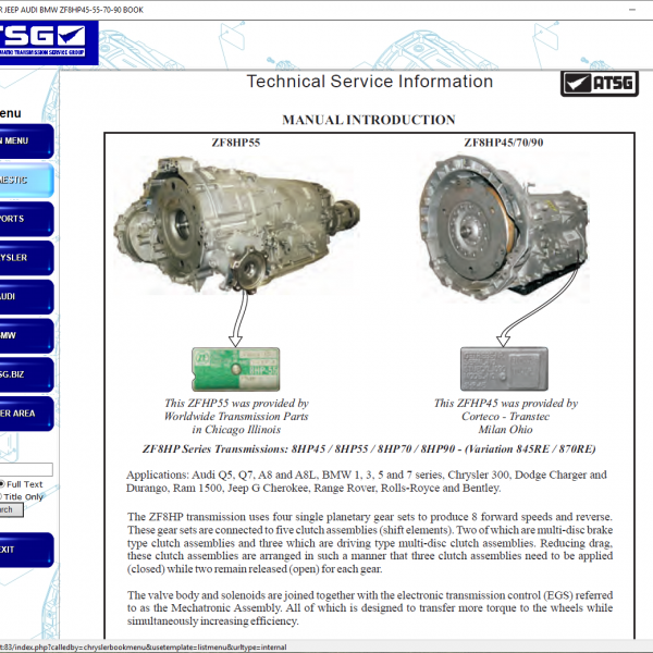
Electronic Parking Brake System Components
EPB control unit (AV151.1)
Parking brake operating element (S1486.1)
Central electrical system (A100.1)
RIO control module (A1358.1)
PFB ATO module (A1357.1)
These components form the electronic control system responsible for activating and monitoring the vehicle parking brake.
Electrical Supply and Fuse Protection
Fuse EPB (F1702.1, terminal 15)
Fuse EPB_1 (F1709.1, terminal 30)
Fuse EPB_2 (F1710.1, terminal 30)
These protected circuits supply the EPB control unit and related electronic components.
CAN Bus and Communication Networks
C-CAN communication network
I-CAN communication through RIO module
CAN topology termination must be respected, including the 120-ohm termination requirement when the EPB ECU is the network end participant.
Pressure Monitoring and Sensor Wiring
Parking brake pressure sensor or pressure switch (B369.1)
Sensor supply circuits
Sensor ground routing
Signal transmission to RIO
Different vehicle variants may use either a pressure sensor or pressure switch depending on brake configuration.
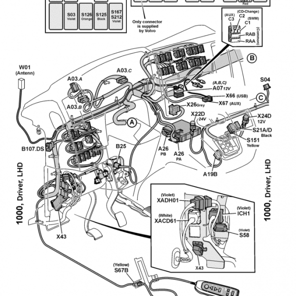
Wiring Harness Interfaces
Compact battery box harness connector (X5490)
Frame harness connector (X6616)
Cab-frame connector (X6302)
Frame separation connector left/right (X6490)
These harness interfaces are required for full diagnostic tracing of the EPB electrical system.
Diagnostic Use Cases
electronic parking brake not engaging
EPB warning light faults
CAN communication brake errors
pressure sensor signal issues
fuse or electrical supply faults
parking brake switch malfunction
ECU communication problems
Compatible Vehicles
TGX
TGS
TGM
TGL
MAN TG3 platform trucks equipped with electronic parking brake system.
Technical Highlights
Complete OEM electronic parking brake wiring diagrams
EPB ECU electrical architecture included
CAN bus communication topology shown
Fuse protection and power routing included
Pressure sensor and switch circuits included
Full harness routing references included
Table of Content
EPB Control Units
Electronic parking brake ECU
RIO module
PFB ATO module
Driver Controls
Parking brake operating element
Electrical Protection
Fuse EPB terminal 15
Fuse EPB terminal 30
Central electrical system
CAN Communication
C-CAN network
I-CAN network
CAN termination logic
Pressure Monitoring
Parking brake pressure sensor
Sensor supply circuits
Sensor ground routing
Wiring Harness Interfaces
Battery box connector
Frame harness connector
Cab-frame connector
Frame separation connectors

Reviews
Clear filtersThere are no reviews yet.