







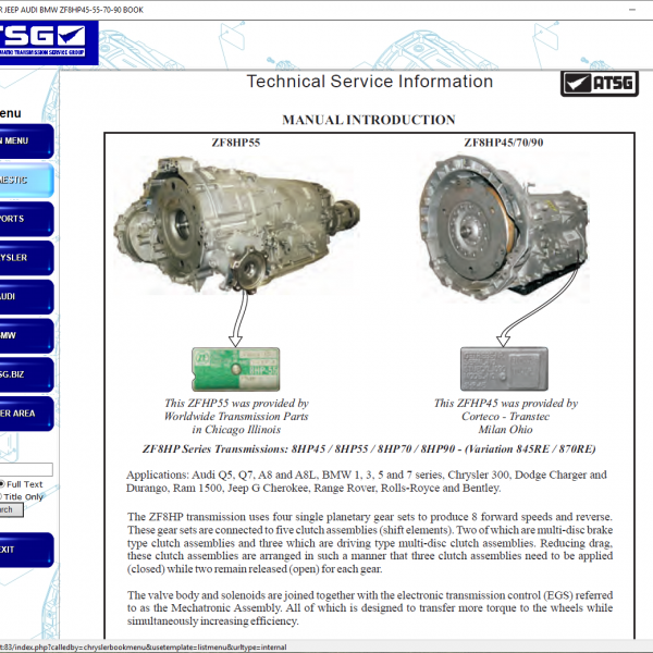
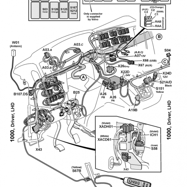
This document includes three full A2-size engineering drawings that map every electrical path of the infotainment system.
Infotainment Control Units
| Component ID | Module |
|---|---|
| AV120.1 | Infotainment Head Unit |
| AV121.1 | Infotainment Display |
| AV122.1PT | Infotainment Button Panel |
| AV127.1PT | Infotainment ICS |
| AV161.1PT | USB / AUX Interface |
| A1363.2 | CVM (Camera & Video Manager) |
| AV006.1 | Front Mirror Camera |
Audio System Coverage
This manual maps the entire multi-channel sound system:
| Speaker | ID |
|---|---|
| Tweeter Right | B380.1PT |
| Tweeter Left | B381.1PT |
| Bass Left | B685.1 |
| Bass Right | B686.1 |
| Broadband Left | B689.1 |
| Broadband Right | B690.1 |
| Center Speaker | BV121.1 |
| Subwoofer | B986.1 |
Including:
-
Line-Out L / R
-
Speaker level outputs
-
Audio ground
-
Subwoofer power & remote on/off
Antenna & RF System
All RF signal paths are mapped with FAKRA & HSD connectors:
| Signal | Connector |
|---|---|
| GPS | FAKRA Code-K (curry) |
| DAB | FAKRA Code-C (blue) |
| FM / AM | FAKRA Code-B (white) |
| Cameras | HSD Code-D / E |
| Ethernet Video | Dual HSD Code-D |
Camera System
| Camera | Connector |
|---|---|
| Rear View Camera 1 | X6544 |
| Rear View Camera 2 | X6543 |
| Front Mirror Camera | AV006.1 |
Includes:
-
Camera data +
-
Camera data –
-
Shield
-
Vcc
-
Ground
Vehicle Data Networks
The infotainment system is integrated into three vehicle data buses:
| Bus | Used For |
|---|---|
| I-CAN | Head unit, CVM, system control |
| H-CAN | High-speed vehicle backbone |
| Ethernet ETH7 / ETH8 | Camera & video streaming |
USB / AUX System
| Pin | Function |
|---|---|
| Data + | USB_D+ |
| Data – | USB_D– |
| V-Bus | 5V |
| GND | Ground |
| Shield | EMI protection |
Located in AV161.1PT USB/AUX module
Power & Fuse Coverage
| Fuse | Function |
|---|---|
| F600.1 | Radio Class 30 |
| F1390.1 | Infotainment |
| F1552.1 | Radio 12V |
Power states:
-
Kl.30 Permanent battery
-
Kl.15 Ignition
-
Wake-Up signals
-
Reset-Out
-
Ground network SYS_groundNet
Body Harness & Connector Network
This manual maps every infotainment cable through the vehicle body:
| Connector | Location |
|---|---|
| X6406 | Left door |
| X6411 | Right door |
| X6429 | Right body |
| X6432 | Left roof |
| X6435 | Right roof |
| XDSRCCSP | Central speaker separation |
| X6537 / X6538 / X6540 | Radio power, speakers, antenna |
These show roof-to-dashboard signal routing, used for antennas, cameras, microphones, and speakers.



Reviews
Clear filtersThere are no reviews yet.