







Vehicle Coverage
| Information | Details |
|---|---|
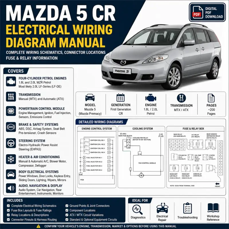
| Vehicle | Mazda 5 / Mazda Premacy |
| Generation | First generation |
| Chassis family | CR |
| Engine type | Four-cylinder petrol |
| Likely engines | 1.8L and 2.0L MZR petrol |
| Most likely 2.0L engine family | LF-series |
| Transmission coverage | Manual and automatic |
| Manual type | Electrical wiring diagram |
| Format | Digital PDF |
| Approximate length | 200 pages |
Engine and Transmission Coverage
The wiring diagrams cover a four-cylinder petrol engine management system with:
- Four individual ignition coils
- Four fuel injectors
- Powertrain control module
- Electronic fuel injection
- Fuel-pump control
- Heated oxygen sensors
- Engine coolant-temperature sensor
- Camshaft-position sensor
- Crankshaft-position sensor
- Throttle-position sensor
- Vehicle-speed input
- EGR control
- Intake and engine-management sensors
- Automatic transaxle control information
Transmission-related coverage includes:
- Manual transmission
- Automatic transmission
- Transaxle-range switch
- Shift-lock system
- Key-interlock system
- Automatic transaxle control
- Transmission-related PCM circuits
The diagrams regularly distinguish between ATX and MTX configurations.
Table of Contents
- General electrical information
- Electrical wiring schematic
- Main power distribution
- Battery power circuits
- Ignition-switched circuits
- Accessory power circuits
- Electrical symbols
- Wire-colour identification
- Connector-terminal views
- Harness symbols
- Component references
- Fuse and relay information
- Main fuse block
- Interior fuse block
- Fuse ratings
- Fuse assignments
- Main engine relay
- Cooling-fan relay
- Fuel-pump relay
- Starter relay
- Headlight relays
- Fog-light relay
- Blower relay
- Air-conditioning relay
- Horn relay
- Rear-window defroster relay
- EHPAS fuse
- ABS and DSC circuits
- Connector and harness information
- Front-to-engine connectors
- Front-to-instrument-panel connectors
- Front-to-rear connectors
- Engine-to-injection connectors
- Instrument-panel-to-rear connectors
- Door harness connectors
- Sliding-door connectors
- Interior-light connectors
- Joint connectors
- Short-cord connectors
- Data-link connector
- Control-module connectors
- Terminal numbering
- Wire colours
- Connector-face views
- Grounding and component locations
- Ground-point identification
- Ground-wire routing
- Engine-compartment ground locations
- Instrument-panel ground locations
- Rear-body ground locations
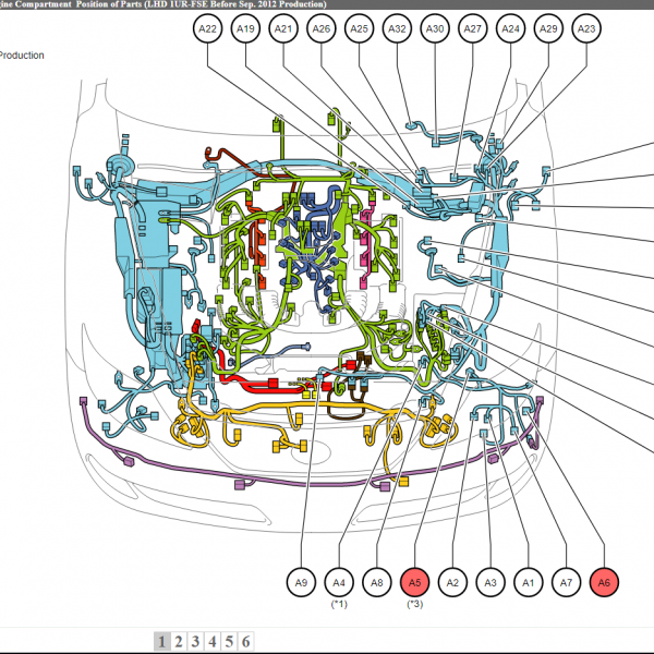
- Harness-routing drawings
- Electrical component locations
- Connector-position illustrations
- Engine electrical systems
- Cooling-fan control
- Fuel-pump system
- Charging system
- Starting system
- Engine-control system
- Ignition circuits
- Fuel-injection circuits
- PCM power supply
- Engine sensors
- Oxygen-sensor circuits
- Generator wiring
- Starter wiring
- Main relay control
- Brake and stability systems
- Antilock braking system
- Dynamic Stability Control
- Wheel-speed sensors
- ABS hydraulic unit
- DSC hydraulic unit
- Brake-light circuits
- High-mounted brake light
- Stability-control communication
- DSC and non-DSC configurations
- Steering systems
- Electro-hydraulic power-assist steering
- EHPAS control module
- Steering-system power supply
- Steering communication circuits
- EHPAS fuse and grounding
- Steering component locations
- Heating and air conditioning
- Manual air conditioning
- Automatic climate control
- Blower motor
- A/C compressor control
- Magnetic clutch
- Climate-control unit
- Heater circuits
- Rear-window defroster
- Heated exterior mirrors
- Automatic A/C variations
- Exterior lighting systems
- High-beam headlights
- Low-beam headlights
- Manual headlight levelling
- Automatic headlight levelling
- Headlight-cleaner system
- Front fog lights
- Rear fog lights
- Parking lights
- Taillights
- Licence-plate lights
- Brake lights
- Turn signals
- Hazard-warning lights
- Exterior illumination
- Interior and body electrical systems
- Body control module
- Power windows
- Power door locks
- Keyless-entry system
- Advanced keyless system
- Immobilizer
- Theft-deterrent system
- Power exterior mirrors
- Heated exterior mirrors
- Sunroof
- Windshield wipers and washers
- Rear wiper and washer
- Horn
- Seat warmers
- Accessory sockets
- Cigarette lighter
- Interior lights
- Map lights
- Cargo-area lighting
- Sliding-door and MPV systems
- Sliding-door circuits
- Door-closer systems
- Power sliding-door variations
- Multiple rear-door harnesses
- Rear power windows
- Door-lock circuits
- Rear-body connector locations
- Safety and security systems
- Airbag system
- Side and curtain airbags
- Supplemental restraint system
- Immobilizer
- Theft-deterrent system
- Keyless-entry system
- Advanced keyless system
- Shift-lock system
- Key-interlock system
- Audio, navigation and display systems
- Audio system
- Car-navigation system
- Rear entertainment system
- Information display
- Instrument cluster
- Rear-view monitor
- Audio connectors
- Display communication wiring
- Navigation and non-navigation variations
Equipment and Trim Variations
This manual is not limited to one specific trim. The diagrams include optional configurations such as:
- Dynamic Stability Control
- Automatic air conditioning
- Advanced keyless entry
- Theft-deterrent system
- Car navigation
- Rear entertainment system
- Sunroof
- Seat warmers
- Heated exterior mirrors
- Rear power windows
- Power sliding doors
- Side and curtain airbags
- Discharge headlights
- Automatic headlight levelling
- Rear-view monitor
Suitable Uses
This manual is suitable for:
- Electrical fault diagnosis
- Short-circuit tracing
- Open-circuit testing
- Fuse and relay identification
- Connector-pin verification
- Ground-point inspection
- Harness repair
- Engine-management diagnosis
- Starting and charging diagnosis
- Lighting-system repair
- Body-electrical troubleshooting
- Optional-equipment installation
- Workshop and technician reference


Reviews
Clear filtersThere are no reviews yet.