






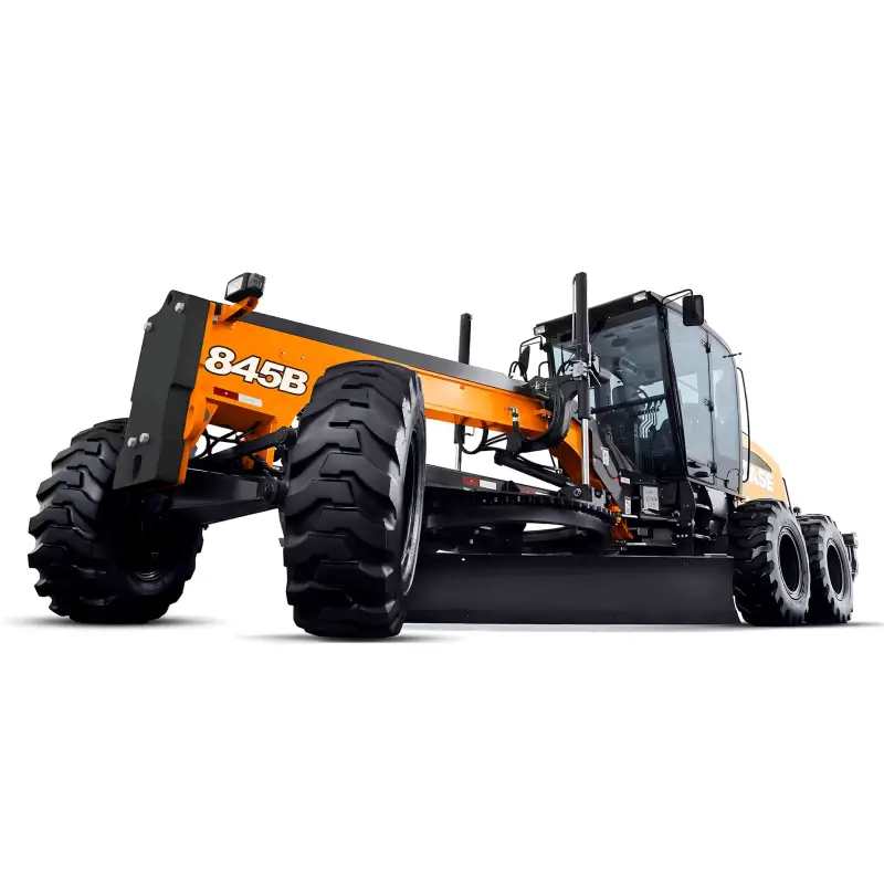

This CASE Grader Front Wheel Drive Functional Scheme FG200 PDF provides the complete electrical and hydraulic layout of the AWD/FWD system used in CASE Series B motor graders.
The document details signal inputs, outputs, and communication protocols between TCU (Transmission Control Unit), ECM (Engine Control Module), and Linde HPV55-02 / HMV75-02 hydraulic components.
Technical Highlights
-
System type: FG200 Front Wheel Drive (AWD configuration)
-
Date: 14 July 2009
-
Primary modules:
-
TCU / ECM (EDC)
-
AWD control switchpad
-
Hydraulic pump (HPV 55-02)
-
Hydraulic motors (HMV 75-02 Left / Right)
-
-
Control logic shown:
-
Motor Displacement Calculation (Task E 50 ms)
-
Pump Displacement Calculation (Task G 50 ms)
-
Motor Control (Task A 10 ms)
-
Pump Control (Task B 10 ms)
-
CAN Bus Data Exchange (Tasks C, I 100 ms)
-
-
Inputs covered:
-
Accelerator, inching, brake pedals
-
Forward/neutral/reverse switches
-
AWD / Creep / Drive Behavior selector
-
Pressure sensors (u16PresFw, u16PresRv)
-
-
Outputs:
-
Solenoid valve control (PWM signals)
-
Proportional displacement valves
-
Pressure dump and high-pressure cut-off
-
-
Operating range:
-
Max pump displacement ±55 cc
-
Max motor torque 10 645 Nm @ 167 rpm
-
System pressure 420 bar (6091 psi) continuous / 500 bar peak
-
-
Communication:
-
CAN J1939 @ 10 ms & 100 ms update rates
-
ECM–TCU integration with drive behavior logic
-
-
Diagram features (page 1):
-
Inputs/Outputs legend (yellow/green blocks)
-
Hydraulic flow paths with charge pump, pilot valve, and main circuit
-
Cooling system sizing notes for max ambient temperature and heat dissipation
-
File Information
-
Publisher: Neubert Engineering
-
System: CASE Series B Grader FWD / AWD Hydraulic System FG200
-
Pages: 1 (Full schematic)
-
Language: English / Technical Symbols (IEC standard)
-
Format: Vector PDF
-
Category: Hydraulic and Electronic System Diagram
Delivery
The download link will be sent to your email instantly after payment.





Reviews
Clear filtersThere are no reviews yet.